Coiled material steel bar grouting connector

A connector and coil technology, applied in structural elements, building components, building reinforcements, etc., can solve the problems of poor concrete mechanical properties, concrete stress concentration, increased damage to prefabricated components, etc., to achieve excellent tensile strength, strong The effect of restraint stress

Active Publication Date: 2015-11-18
BEIJING UNIV OF TECH
View PDF9 Cites 3 Cited by
  • Summary
  • Abstract
  • Description
  • Claims
  • Application Information

AI Technical Summary

Problems solved by technology

[0003] Steel connectors, including sleeve connectors and mechanical connectors, have been widely used in the connection of steel bars between prefabricated components, and have the advantages of stable axial load transmission, convenient construction, and green construction; however, The traditional metal sleeve steel connectors have a large diameter and are closely distributed at the beam-column joints with high reinforcement ratios, which makes the concrete layer between the sleeves thinner and the gradation of the concrete layer is poor. The mechanical properties of concrete are poor; in addition, the damage of cast-in-place components under earthquake loads is mostly the continuous cracking of concrete, and the existence of multiple metal sleeves in prefabricated components makes the building components produce a rigidity in the sleeve area. In a large area, under load, the sleeve area is difficult to coordinate with the deformation of the surrounding materials, and the stress concentration of the concrete on both sides of the sleeve is likely to be concentrated, brittle failure occurs in advance, and the concrete at the joint cannot fully exert the mechanical properties of the material. Increased the probability of damage to prefabricated components under seismic loads

Method used


Image

  • Coiled material steel bar grouting connector
  • Coiled material steel bar grouting connector
  • Coiled material steel bar grouting connector

Examples


Embodiment Construction

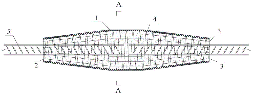
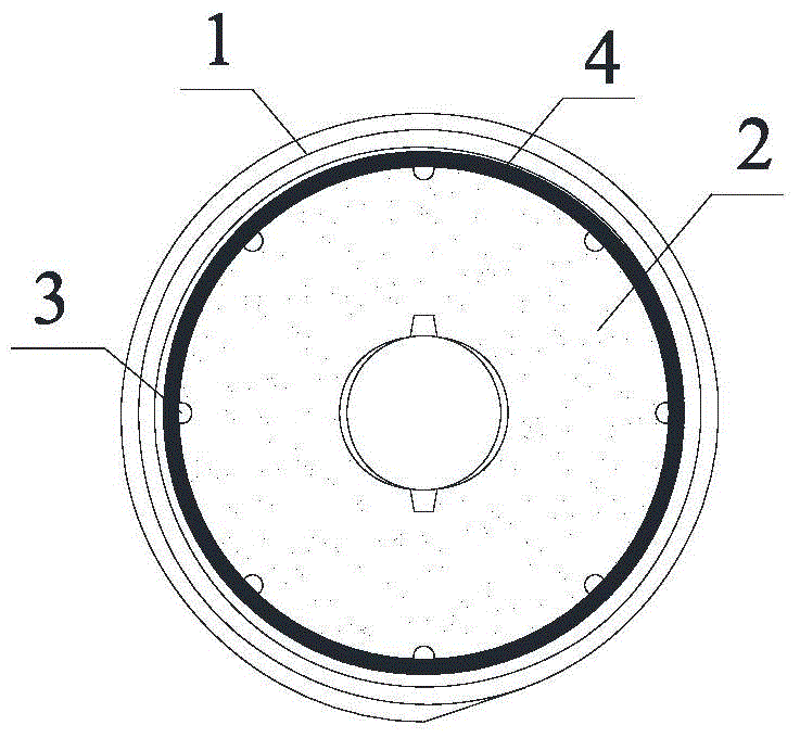
[0016] When the building structure needs to connect steel bars between components, the coil grouted steel bar connector of the present invention can be used to achieve the mechanical properties not lower than the direct connection of steel bars. The present invention can not only be used in the design and construction of new buildings, but also in the seismic reinforcement of existing buildings, such as Figure 1-Figure 4 As shown, among them, figure 1 It is a structural schematic diagram of the present invention, figure 2 for figure 1 The A-A section diagram, image 3 It is another structural schematic diagram of the present invention, Figure 4 for image 3 B-B sectional view; specifically, coil 1, expansion mortar 2, support longitudinal reinforcement 3, support transverse reinforcement 4, steel reinforcement 5, shear groove and support transverse reinforcement.

[0017] Among them, the roll material is a soft material that can be rolled, such as figure 1 and figur...


PUM


Abstract

The invention discloses a coiled material steel bar grouting connector, and belongs to the field of a preassembled building structure in the civil engineering. The coiled material steel bar grouting connector comprises a coiled material, expansive mortar and a support frame, wherein the coiled material is a soft coiled building material; the support frame is provided with transverse and/or longitudinal stress bars; the expansive mortar is connected with steel bars; the coiled material is wound around the outer surface of the support frame; and the expansive mortar is injected into the coiled material. The coiled material steel bar grouting connector can be used for connecting steel bars between assembled components. The coiled material steel bar grouting connector can be arranged at a connecting joint part of the assembled components in the engineering, can bear the axial tension generated by building components under the load effect, and can enable the building material at the joint part to be subjected to coordinate deformation. The coiled material steel bar grouting connector has the advantages that the structural form is simple and free; the mechanical property is reliable; the installation is convenient and fast; the industrialization can be realized; and the coiled material steel bar grouting connector has wide engineering application prospects.

Description

technical field [0001] The invention relates to the field of prefabricated building structures in civil engineering, in particular to a coil steel bar grouting connector. Background technique [0002] Rolled materials for construction, such as carbon fiber cloth and glass fiber cloth, are soft in texture and can be curled into various shapes at will, but their mechanical properties are excellent, especially their tensile properties, which even exceed the properties of ordinary steel; similarly, steel Stranded wire is also flexible and bendable, but has better tensile properties. [0003] Steel connectors, including sleeve connectors and mechanical connectors, have been widely used in the connection of steel bars between prefabricated components, and have the advantages of stable axial load transmission, convenient construction, and green construction; however, The traditional metal sleeve steel connectors have a large diameter and are closely distributed at the beam-column ...

Claims


Application Information

Patent Timeline
Patent Type & Authority Applications(China)
IPC IPC(8): E04C5/16
Inventor 许成顺江志伟杜修力路德春
Owner BEIJING UNIV OF TECH
Why Eureka
Try Eureka