Hydraulic coupler

A technology of hydraulic coupler and hydraulic oil pump, which is applied in the direction of fluid transmission, belt/chain/gear, mechanical equipment, etc., can solve the problems of difficult impeller design and processing, low working efficiency and large volume of hydraulic coupling, etc. Achieve fully adjustable starting performance, limited safety protection, and small size.

Inactive Publication Date: 2015-11-18
HOHAI UNIV CHANGZHOU
View PDF6 Cites 0 Cited by
  • Summary
  • Abstract
  • Description
  • Claims
  • Application Information

AI Technical Summary

Problems solved by technology

However, due to the disadvantages of low working efficiency, large volume, speed difference between the prime mover and the working machine, and difficulty in impeller design and processing, the hydraulic coupling is more prominent, especially for high-power hydraulic couplings.

Method used


Image

  • Hydraulic coupler

Examples


Embodiment Construction

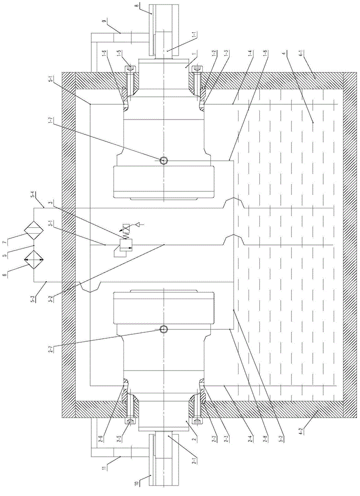
[0019] Such as figure 1As shown, a hydraulic coupling includes a hydraulic oil pump 1, a hydraulic motor 2, a proportional relief valve 3, an oil tank 4, a connecting pipeline 5, a cooler 6, a filter 7, a first speed sensor 9 and a second speed sensor 11. The fuel tank 4 includes a fuel tank right side plate 4-1 and a fuel tank left side plate 4-2, and the connecting pipeline 5 includes a first connecting pipeline 5-1, a second connecting pipeline 5-2, and a third connecting pipeline 5-3 and the fourth connection pipeline 5-4; the hydraulic oil pump 1 includes an oil pump input shaft 1-1, an oil pump suction port 1-3, an oil pump outlet port 1-6, and an oil pump leakage port 1-7, and the hydraulic oil pump 1 is installed in the oil tank 4 The inner side is installed on the right side plate 4-1 of the oil tank through the oil pump installation screws 1-5, and an oil pump end face gasket 1-2 is arranged between the end face of the hydraulic oil pump 1 and the right side plate 4...


PUM


Abstract

The invention discloses a hydraulic coupler. The hydraulic coupler comprises a hydraulic oil pump, a hydraulic motor, a connection pipeline, a proportional overflow valve, an oil tank, a cooler, a filter, a first revolution speed transducer, a second revolution speed transducer and the like. The hydraulic coupler has the characteristics that the work efficiency is high, the size is small, loading limit safety protection is achieved, starting performance can be fully adjusted, stepless speed regulating can be achieved, and the speed regulating range is wider. The hydraulic coupler is provided with the cooler and the filter so that the reasonable temperature and cleanliness of working oil can be maintained; meanwhile, due to the fact that the first revolution speed transducer and the second revolution speed transducer are mounted on an input shaft and an output shaft of the hydraulic coupler respectively, analysis and processing can be conducted by collecting information of the two revolution speed transducers; the control curve of the proportional overflow valve is designed, so that the starting process of a working machine is controlled more accurately. The hydraulic coupler is applied to the starting process of a steam turbine and a draught fan, so that the functions of smooth starting, limit safety protection, speed regulating and the like in the working process of the steam turbine and the draught fan are achieved; the hydraulic coupler has a broader application prospect.

Description

technical field [0001] The invention relates to a coupler used in the starting process of a power unit, in particular to a hydraulic coupler, which belongs to the technical field of electric and electromechanical. Background technique [0002] At present, in the start-up process of steam turbines and fans, hydraulic couplings are widely used to achieve a smooth start-up of the working process. However, due to the disadvantages of low working efficiency, large volume, speed difference between the prime mover and the working machine, and difficult design and processing of the impeller, the hydraulic coupling, especially the high-power hydraulic coupling, has more prominent shortcomings. In order to overcome the above shortcomings of the hydraulic coupling, this application proposes that a hydraulic coupling is mainly composed of a hydraulic oil pump, a hydraulic motor, a proportional relief valve, a cooler, a filter, a first speed sensor and a second speed sensor, etc. On the...

Claims


Application Information

Patent Timeline
Patent Type & Authority Applications(China)
IPC IPC(8): F16H41/00F16H41/24F16H41/30
CPCF16H41/00F16H41/24F16H41/30
Inventor 钱雪松
Owner HOHAI UNIV CHANGZHOU
Why Eureka
Try Eureka