Eureka AIR delivers breakthrough ideas for toughest innovation challenges, trusted by R&D personnel around the world.

A temperature adjustment system for controlling the temperature of transmission oil through cooling medium

A transmission oil and cooling medium technology, applied in the direction of gear lubrication/cooling, components with teeth, transmission parts, etc., can solve the problems of increased emissions, large fluctuations in transmission oil temperature, waste of cooling performance, etc., to achieve accurate Control, accurate transmission oil temperature, the effect of reducing the burden

Active Publication Date: 2017-10-20
DONGFENG FUJI THOMSON THERMOSTAT
View PDF10 Cites 0 Cited by
  • Summary
  • Abstract
  • Description
  • Claims
  • Application Information

AI Technical Summary

Problems solved by technology

Such a control strategy has the following disadvantages: 1. In a small cycle, the coolant and the transmission oil do not participate in heat exchange, which will cause waste of this part of the cooling performance
At the same time, at idle speed, this part of the coolant will also indirectly increase the burden on the engine cooling system, resulting in a long cold start time and increased emissions.
2. When the transmission oil and the coolant exchange heat, the flow of the cooled oil is controlled. Such indirect control will cause large fluctuations in the transmission oil temperature, which is not conducive to quickly reaching the appropriate temperature.

Method used


Image

  • A temperature adjustment system for controlling the temperature of transmission oil through cooling medium
  • A temperature adjustment system for controlling the temperature of transmission oil through cooling medium
  • A temperature adjustment system for controlling the temperature of transmission oil through cooling medium

Examples


Embodiment Construction

[0024] The present invention will be further described below in conjunction with the accompanying drawings.

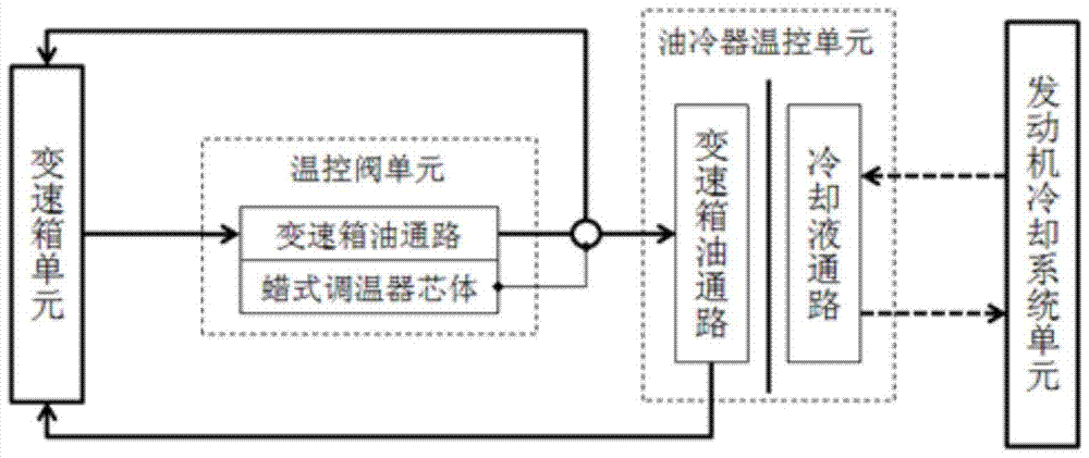
[0025] Such as figure 1 As shown, the temperature control principle of the traditional gearbox temperature adjustment system is:

[0026] When the transmission oil is low temperature: the transmission oil flows in from the oil inlet of the temperature control valve body and flows out from the oil outlet. The valve body flows to the oil outlet, forming a small circulation. During this process, the coolant in the engine cooling system has been flowing in the oil cooler, and no heat exchange occurs at this time.

[0027] When the transmission oil rises to the set temperature: the core of the wax-type thermostat feels the high oil temperature, the valve opens, and the transmission oil flows into the oil cooler control unit, forming a large cycle. At this time, the transmission oil and the cooling fluid exchange heat in the oil cooler control unit to reduce the oil tempe...


PUM


Abstract

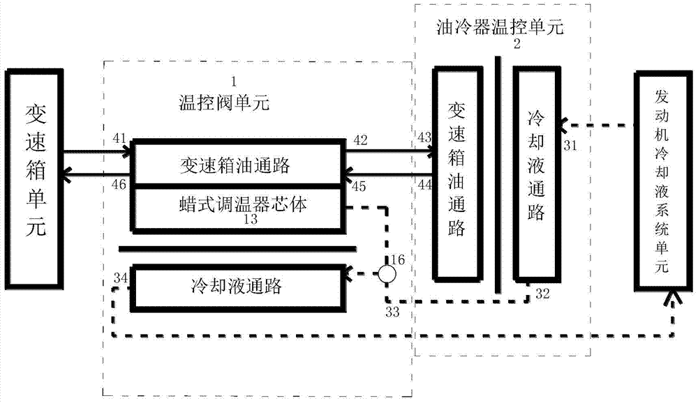
The invention relates to the technical field of cooling of gearbox oil, in particular to a temperature regulation system for controlling the temperature of gearbox oil through cooling media. According to the temperature regulation system, a control device is not arranged in a gearbox oil loop, the gearbox oil is cycled in the system all the time, and the flow is not changed along with the change of the temperature. However, a flow control device is arranged in a cooling liquid loop of the temperature regulation system and acts along with the change of the temperature of a gearbox oil way, so that the magnitude of the flow of cooling liquid in the cooling liquid loop is controlled. The gearbox oil flows in the temperature regulation system with constant flow and transmits heat to a wax type thermostat core which controls the magnitude of the flow of the cooling liquid while sensing the temperature of the gearbox oil. According to the temperature regulation system, the flow of the cooling liquid participating in heat exchange is controlled directly to enable the temperature fluctuation of the gearbox oil to be minimized, and the flow of the cooling liquid is limited when the temperature of the gearbox oil is low, so that loads of an engine cooling system are reduced; finally, the purpose that the temperature of the gearbox oil is more accurately controlled is achieved.

Description

technical field [0001] The invention relates to the technical field of transmission oil cooling, in particular to a temperature adjustment system for controlling the temperature of transmission oil through a cooling medium. Background technique [0002] Automatic transmission oil is not only the transmission oil of the hydraulic torque converter, but also the lubricating oil of the gear structure and the hydraulic oil of the shifting device in the automatic transmission. During use, due to the slipping phenomenon of clutches and brakes inside the gearbox and the frictional heat generated during mechanical transmission, the temperature of the gearbox oil will continue to rise, which will accelerate the oxidation of the oil and produce carbon deposits, which will eventually lead to Stuck. Therefore, the current automatic transmission is generally equipped with a set of automatic transmission oil temperature control system. [0003] Since only automatic transmission oil circu...

Claims


Application Information

Patent Timeline
Patent Type & Authority Patents(China)
IPC IPC(8): F16H57/04
CPCF16H57/0413F16H2700/00
Inventor 朱晶伟夏宝柱姜兴
Owner DONGFENG FUJI THOMSON THERMOSTAT
Why Eureka
Eureka Blog
Learn More