[0029] The following are specific embodiments of the present invention in conjunction with the accompanying drawings to further describe the technical solutions of the present invention, but the present invention is not limited to these embodiments.
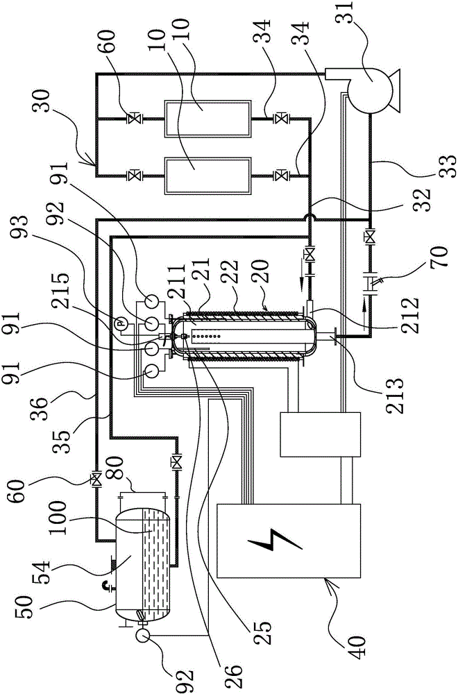
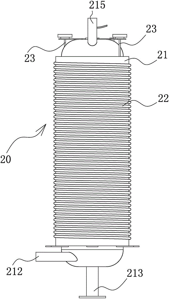
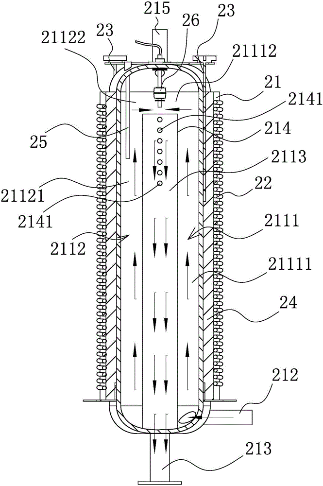
[0030] The present invention protects an electromagnetic heating boiler system, which has a heating furnace 20 (heating boiler) and a circulation mechanism 30 for circulating an organic heat carrier, which is convenient for resource regeneration.
[0031] The electromagnetic heating boiler system uses electromagnetic heating to heat the organic heat carrier such as heat transfer oil 100, and transmits the heat generated after heating to the heating equipment 10. The heating furnace 20 is a low pressure (under normal pressure or lower) Special industrial furnace that can provide high temperature heat energy under pressure).
[0032] The existing industrial heating furnace 20 that uses an organic heat carrier for heating has an unreasonable structural design, unsatisfactory heating effect, and cannot realize the recycling of the organic heat carrier, and the degree of automation is not high, which cannot meet the efficient operation requirements of the workshop. Therefore, it is necessary to design a relatively reasonable electromagnetic heating boiler system.
[0033] Such as Figure 1 to Figure 3 As shown, the electromagnetic heating boiler system includes:
[0034] The heating device 10 is set to at least one;
[0035] The heating furnace 20 has a furnace body 21 in which a heating channel for conveying the heat transfer oil 100 is provided, and an electromagnetic heating coil 22 for heating the heat transfer oil 100 in the heating channel is wound on the outer side wall of the furnace body 21;
[0036] The circulation mechanism 30 is used to send the heat transfer oil 100 discharged from the heating furnace 20 to the heating device 10, and send the heat transfer oil 100 after the heat is absorbed by the heating device 10 back to the heating furnace 20 to continue heating;
[0037] The control mechanism 40 is electrically connected to the electromagnetic heating coil 22 and used to control the opening and closing of the electromagnetic heating coil 22.
[0038] In the present invention, the electromagnetic heating boiler system is an electromagnetic heating organic heat carrier boiler system, which uses electromagnetic heating to heat the organic heat carrier. Preferably, the heated organic heat carrier is heat transfer oil 100 to generate heat, Storage and delivery are more efficient.
[0039] In the initial state, the electromagnetic heating boiler system has a reasonable structural design. It mainly includes a control mechanism 40, a heating furnace 20, a circulation mechanism 30, and a heating device 10. The heating furnace 20 uses electromagnetic heating to heat the organic heat carrier (heat transfer oil 100) For heating, because the heat transfer oil 100 itself has the properties of resistance to thermal cracking, chemical oxidation, good heat transfer efficiency, and good thermal stability, and the heat transfer oil 100 also has the characteristics of energy saving, convenient transportation, and high temperature generation under low vapor pressure. The heat-conducting oil 100 and the electromagnetic heating coil 22 are closely matched, the heat-conducting oil 100 is heated quickly, the heating effect is greatly improved, and the energy utilization rate is greatly improved. At the same time, it does not pollute the environment and also ensures the safety performance of the heating furnace 20.
[0040] In this case, the control mechanism 40 can realize the automatic control of the overall system on, off, and tentatively. The setting of the circulation mechanism 30 allows the organic heat carrier to circulate continuously. When in use, the user only needs to access the power supply and the medium (heat transfer Oil 100) import and export pipelines and some electrical interfaces are sufficient, and the degree of automation is high.
[0041] Specifically, the heating process of the electromagnetic heating boiler system is as follows: the unheated heat transfer oil 100 enters the heating channel of the heating furnace 20 through the circulation mechanism 30; then the control mechanism 40 transmits the work to the electromagnetic heating coil 22 to turn on (heating) Signal. At this time, the electromagnetic heating coil 22 is energized. Due to the eddy current effect, heat is generated in the heating channel and the conveyed heat transfer oil 100 is heated; the heated heat transfer oil 100 is sent into the circulation mechanism 30 through the outlet of the furnace body 21, the circulation mechanism 30 and then send the heated heat transfer oil 100 to the heating device 10; then, the circulation mechanism 30 sends the heat transfer oil 100 after heat absorption by the heating device 10 back to the heating channel of the heating furnace 20 to continue heating. In the working process, the various parts are closely coordinated, without manual involvement, and a high degree of automation.
[0042] The above is a working cycle of the heating boiler system, which repeats itself to realize the continuous transfer of heat/heat energy. When the heat equipment 10 is working, it continuously absorbs the heat of the heat transfer oil 100. Preferably, the circulation mechanism 30 does not stop during a single working cycle. The work efficiency is further improved, and the present invention has positive promotion significance for reducing energy consumption and environmental protection.
[0043] The heating furnace 20 in the present invention is a new, safe, efficient, and energy-saving organic heat carrier boiler, and also a special industrial furnace that can provide high temperature heat energy at low pressure (under normal pressure or lower pressure). The electromagnetic heating The boiler system is a liquid-phase closed circuit system that uses electricity as the heat source and the heat transfer oil 100 as the heat carrier. The circulation mechanism 30 is used to realize the liquid phase circulation. After the heat energy is delivered to the heating equipment 10, it returns to the reheated liquid phase closed circuit system. The difference in oil return temperature is 20-40 degrees, that is to say, the operating temperature can be reached only by heating the temperature difference of 20-40 degrees. Preferably, the difference between the oil outlet temperature and the return temperature in this case is 30 degrees or 35 degrees to make the heating boiler system work higher efficiency.
[0044] At the same time, the electromagnetic heating boiler system does not require water treatment equipment and has no heat loss such as running, emitting, dripping, and leakage of the steam boiler. The heat utilization rate is high. Compared with the steam boiler, the energy saving is more than 50%, compared with the electric heating method. For the organic heat carrier furnace system, the electromagnetic heating method in this case is faster and therefore more efficient.
[0045] During operation, the furnace body 21 (that is, the heating channel) is filled with the heat transfer oil 100. After the heat transfer oil 100 is induction heated by the electromagnetic heating coil 22, it is transported to the station through the circulation mechanism 30 (preferably provided with a pipeline), and is heated The furnace 20 can realize continuous heat transfer in cycles, so that the temperature of the heated object (using the heating device 10) is increased, and the heating process requirements are met.
[0046] Further, the heating channel has a total oil inlet 212 and a total oil outlet 213 provided on the furnace body 21. The heating channel is divided into a first heating channel 2111 and a second heating channel 2112. The first heating channel 2111 and the second heating channel The oil inlets of the channels 2112 are respectively connected in series with the main oil inlet 212, and the oil outlets of the first heating channel 2111 and the second heating channel 2112 meet at the main oil outlet 213.
[0047] In this case, the heating furnace 20 adopts a method of splitting electromagnetic heating and then collectively sending out heat. Two heating channels are provided inside the heating furnace 20 for oil feeding and heating, so that the overall heat transfer oil 100 has a larger flow rate. The heat transfer oil 100 of the branch stream is heated more uniformly, and the heat carried by the heat transfer oil 100 (organic heat carrier) is effectively increased within the same heating time, heating is more sufficient, and the heating efficiency is greatly improved.
[0048] Furthermore, the oil outlets of the first heating channel 2111 and the second heating channel 2112 meet at the main oil outlet 213 through the third heating channel 2113. A central pipe 214 is inserted in the middle of the furnace body 21 and the main oil outlet 213 is opened. At the end of the central pipe 214, the third heating channel 2113 passes through the middle of the central pipe 214, and the first heating channel 2111 and the second heating channel 2112 are respectively arranged between the outer peripheral side of the central pipe 214 and the inner side wall of the furnace body 21.
[0049] The arrangement of the central pipe 214 is convenient for installation, disassembly and replacement, and the addition of the third heating channel 2113 makes the heat transfer oil 100 heat more evenly, and the heating time is longer, and also makes the heat transfer oil 100 in the heating channel flow more smoothly and improve heat Conversion efficiency, improve heating efficiency.
[0050] Specifically, the first heating channel 2111 is composed of a first sub-channel 21111 and a second sub-channel 21112 that are connected in sequence, and the second heating channel 2112 is composed of a third sub-channel 21121 and a fourth sub-channel 21122 that are connected in sequence. The oil inlets of a sub-channel 21111 and a third sub-channel 21121 are respectively connected in series with the main oil inlet 212, and the oil outlets of the second sub-channel 21112 and the fourth sub-channel 21122 are simultaneously connected with the oil inlet of the third heating channel 2113. The first sub-channel 21111, the third sub-channel 21121, and the third heating channel 2113 are arranged axially in parallel in the outer cylinder, and the second sub-channel 21112 and the fourth sub-channel 21122 are arranged on the same side and perpendicular to the first sub-channel 21111, respectively. The heat transfer oil 100 in the first sub-channel 21111 and the third sub-channel 21121 flow in the same direction, the heat transfer oil 100 in the second sub-channel 21112 and the fourth sub-channel 21122 flow in opposite directions, and the heat transfer oil 100 in the third heating channel 2113 flows in the same direction. The flow direction of the heat transfer oil 100 in the first sub-channel 21111 is opposite.
[0051] The present invention adopts a curved heating channel structure to make the heat transfer oil 100 flow smoothly, the heat distribution in the heating furnace 20 is relatively uniform, the heating time is longer, the heat transfer oil 100 absorbs more heat, the heating efficiency is further improved, and the work efficiency is improved .
[0052] In addition, the central pipe 214, the furnace body 21 and the various heating channels cooperate with each other, so that the heat transfer oil 100 enters the furnace body 21 (heating furnace 20) from the main oil inlet 212, and then rises in a vortex shape against the inner wall of the furnace, and then passes through The central pipe 214 is discharged downward from the main oil outlet 213, which improves the heat exchange efficiency and ensures the heating effect.
[0053] In order to promote the heat exchange of the heat transfer oil 100, preferably, a plurality of turbulence holes 2141 communicating with the first heating channel 2111 and the second heating channel 2112 and used to generate turbulence are opened on the outer side wall of the central pipe 214. The addition of the turbulent holes 2141 makes the corresponding parts of each heating channel form turbulent flow, which greatly promotes the heat exchange of the heat transfer oil 100 and improves the heating efficiency.
[0054] In order to make the distribution of turbulent holes 2141 more reasonable, the turbulent vortex is more stable. Further, the turbulent flow holes 2141 are arranged on the outer side wall of the central pipe 214 in multiple rows along the axial direction of the furnace body 21. As a preferred solution, it is preferable that the turbulent holes 2141 are arranged vertically in three or four rows, and several rows of turbulent holes 2141 are evenly distributed on the outer side wall of the central pipe 214, so that the turbulent holes 2141 generate turbulent stability and promote each heating channel The heat transfer oil 100 heat exchange ensures the heating efficiency of the overall heating boiler system.
[0055] As an improvement, copper tubes (not shown in the figure) are preferably tightly installed on the outer side walls on both sides of the furnace body 21, and each copper tube is tightly inserted with a temperature measuring needle 23 electrically connected to the control mechanism 40, The two temperature measuring needles 23 have different lengths, and the copper tube is filled with heat transfer oil 100.
[0056] In this case, temperature measuring needles 23 with different lengths are installed on both sides of the furnace body 21 to detect the surface temperature of the furnace body 21 (heating furnace 20), that is, to detect the temperature inside the heating furnace 20 to ensure the stable operation of the heating furnace 20 Sex.
[0057] At present, most of the temperature measuring probe 23 on the market is made of a metal that generates self-heating when exposed to a magnetic field. If it directly touches the furnace wall for detection, the probe's detection value is its self-heating value plus the furnace wall. The wall temperature value will make the detected value higher overall and the error will be larger.
[0058] In the present invention, a copper tube protection scheme is adopted, and copper is a metal that does not generate self-heating in a magnetic field. We place the temperature measuring needle 23 in a copper tube with one end open and one end closed. The copper tube has a shielding effect on the magnetic field, and the temperature measuring needle 23 inside will not generate self-heating.
[0059] Fill the copper pipe with heat transfer oil 100 and install it on the surface of the outer wall of the furnace body 21. Since the heat transfer oil 100 has a good heat transfer effect, the temperature measuring needle 23 detects the temperature of the heat transfer oil 100, which is equivalent to the temperature of the furnace body 21. Indirect detection was performed. The temperature measuring needle 23 preferably has a temperature measuring sensor. After detection, the temperature measuring sensor sends a signal to the control mechanism 40. When an abnormal temperature of the furnace body 21 is detected, a closed loop response is performed to adjust the heating furnace 20 in time to ensure the normal operation of the boiler. The method makes the detection more accurate and the error is smaller.
[0060] Preferably, a thermal insulation cotton layer 24 is sealed and covered on the outer side wall of the furnace body 21, and the electromagnetic heating coil 22 is tightly wound and wrapped around the thermal insulation cotton layer 24.
[0061] The above-mentioned thermal insulation cotton layer 24 is sealed and arranged on the outer side wall of the furnace body 21. The thermal insulation cotton layer 24 is made of tightly arranged thermal insulation cotton. The electromagnetic heating coil 22 is wound in an orderly manner outside the thermal insulation cotton layer 24 to prevent heat conduction in the heating channel. Oil 100 performs high-frequency electromagnetic heating, which has good heating effect and is not easy to age after long-term use, ensuring the service life of the equipment. Moreover, the arrangement of the thermal insulation cotton layer 24 makes the heat transfer efficiency of the heat transfer oil 100 in the heating channel higher and delays the dissipation of heat.
[0062] Preferably, an adjustment port 215 for adjusting the pressure in the heating channel is provided on the top of the furnace body 21, and an oil level gauge 25 located directly below the adjustment port 215 and extending into the heating channel is provided in the furnace body 21. A thermometer 26 for detecting the oil temperature is also inserted in 21, and the thermometer 26 partially extends into the first heating channel 2111 or the second heating channel 2112.
[0063] This structural design makes the layout of the heating furnace 20 more reasonable. The adjustment port 215 is convenient for adjusting the internal pressure of the furnace body 21. An oil level gauge 25 is placed in the center of the furnace body 21 to monitor the oil level in real time, and one is placed on the side of the furnace body 21. The thermometer 26 deep into the furnace body 21 can monitor the oil temperature in real time, making the heating process controllable.
[0064] In this case, the structure of the heating furnace 20 is mainly composed of a furnace body 21, a thermal insulation cotton layer 24, an electromagnetic heating coil 22 and various detection mechanisms. The furnace body 21 has a double-layer structure with a central pipe 214 inside. Preferably, the main oil inlet and the main oil outlet are both arranged at the bottom and/or side of the furnace body 21. After the heat transfer oil 100 enters the furnace body 21, it is attached to the furnace wall It rises in a vortex shape and discharges downwards through the central pipe 214 of the furnace body 21. The turbulent hole 2141 on the central pipe 214 is a small hole. Its function is to form turbulent flow and promote heat exchange. The installation of all the above structures promotes The heat exchange in the furnace body 21 improves the heating efficiency.
[0065] In addition, the heating furnace 20 closely cooperates with the control mechanism 40 and the circulation mechanism 30, so that the electromagnetic heating boiler system has a complete operation control and safety monitoring device, can implement automatic control, and can obtain a higher temperature under a lower operating pressure. Working temperature, high heating efficiency, precise temperature control, this electromagnetic heating boiler system can save energy consumption, cost saving and easy maintenance for most enterprises, the structure has no vulnerable parts, and the work is stable and reliable.
[0066] Preferably, there are two heating equipments 10, and the circulation mechanism 30 includes a circulating pump 31 and a plurality of circulating pipes. The circulating pipes are divided into an oil inlet pipe 32, an oil outlet pipe 33, and a one-to-one correspondence with the two heating equipment 10 Two heat pipes 34, the oil inlet pipe 32 is connected to the main oil inlet, the oil outlet pipe 33 is connected to the main oil outlet, the two heat pipes 34 are connected in parallel, and the heat device 10 is set in the middle of the corresponding heat pipe 34 , The oil outlet pipe 33, the single heat pipe 34, and the oil inlet pipe 32 are arranged in sequence and the three are enclosed to form a heat closed circuit. The circulation pump 31 is installed on the oil outlet pipe 33 and used to realize the liquid phase circulation of the heat closed circuit. , The circulating pump 31 is electrically connected to the control mechanism 40.
[0067] The thermal equipment 10 is closely matched with the corresponding circulating pipes, and the parallel arrangement scheme is adopted to ensure that the work does not interfere with each other, and the stability of the work is ensured. During the continuous feeding and unloading of the heat transfer oil 100 by the circulating mechanism 30, The heating device 10 gradually reaches the expected temperature value, and the overall working process is smooth and reliable.
[0068] In this case, the circulating pump 31 (circulating oil pump) is used to force the liquid phase to circulate, and the heat generated by the heating furnace 20 is transferred to the heating equipment 10, and then the heat transfer oil 100 (organic heat carrier) returns to the heating furnace 20 for reheating and circulating The arrangement of the pump 31 provides a stable conveying force for the flow of the heat transfer oil 100 in the above-mentioned circulation pipeline, so that the equipment works smoothly and improves the stability.
[0069] Moreover, the control mechanism 40 can control the circulating pump 31 to be in a working state or a non-working state, and further control its speed, so that the heating boiler system works more reliably.
[0070] Further, combine Figure 4 As shown, the electromagnetic heating boiler system also includes an oil storage cylinder 50 for transporting the heat transfer oil 100. The oil storage cylinder 50 is provided with an oil storage cavity for storing the heat transfer oil 100, and an oil injection port 51 is provided on the oil storage cylinder 50. , An overflow port 52 and at least one exhaust port 53, the overflow port 52 is arranged on the side of the oil storage cylinder 50 and communicates with the oil storage cavity so that a high groove 54 is formed above the oil in the oil storage cavity, the oil injection port 51, the drain The steam ports 53 are arranged above the oil storage cylinder 50 and communicate with the high tank 54 respectively. The circulation pipeline also includes an oil injection pipe 35 and an oil return pipe 36. The oil injection pipe 35 is connected in parallel with the heat pipe 34 and is respectively connected with the oil inlet pipe 32 and the oil storage pipe. The oil cavity is connected. The oil return pipe 36 is connected in parallel with the heat pipe 34 and communicates with the oil outlet pipe 33 and the oil storage cavity respectively. The oil injection pipe 35, the oil inlet pipe 32, the oil outlet pipe 33, and the oil return pipe 36 are arranged in sequence and the four Enclosed to form a closed circuit for oil supply.
[0071] The above-mentioned oil injection port 51 is used to connect an external oil tank and is used to inject the heat transfer oil 100 into the oil storage cavity. The oil storage cavity is used to temporarily store the heat transfer oil 100 and send the heat transfer oil 100 into the heating furnace 20 through the oil injection pipe 35, overflowing The setting of the port 52 effectively prevents the oil storage cavity from being filled, so that it generates a high-position groove 54. The high-position groove 54 and the steam exhaust port 53 cooperate with each other to accommodate the thermal expansion of the heat transfer oil 100 and empty the newly filled product (heat transfer The light components in the oil 100) and the low-boiling substances produced during operation, nitrogen sealing, etc.
[0072] After the work is completed, the above-mentioned closed oil supply circuit can also be used to recover the heat transfer oil 100 into the oil storage cavity to improve the utilization rate and the working reliability of the equipment.
[0073] Preferably, each circulation pipeline is provided with an on-off valve 60 for opening or closing the circulation pipeline, and the oil outlet pipeline 33 is provided with an oil filter 70 for filtering the heat transfer oil 100 near the main oil outlet. Preferably, both ends of the heating device 10 are provided with on-off valves 60, so that the device control is more accurate and the work efficiency is higher. The setting of the oil filter 70 makes the heat transfer oil 100 heated each time relatively pure. It is further preferred that the oil filter 70 is a Y-type oil filter to improve the heat exchange rate and the heating efficiency of the heating furnace 20.
[0074] The setting of the on-off valve 60 makes the opening and closing of each circuit easier and faster. When the heating device 10 needs to be heated, the on-off valve 60 is controlled to close the oil return pipeline 36 and the oil injection pipeline in the oil supply circuit. 35 is disconnected, at this time the heat closed circuit is turned on; after the equipment stops working, the switch valve 60 will be disconnected with the heat pipe 34, at this time the heat transfer oil 100 discharged from the heating furnace 20 is sent back to the storage through the oil return pipe 36 In the oil cavity, the operation is convenient and the practicability is strong.
[0075] Preferably, a liquid level gauge 80 for testing the oil level of the oil storage cavity is provided on the oil storage cylinder 50, and the control mechanism 40 is connected to the liquid level gauge 80 through an oil level alarm 92. Further, the control mechanism 40 in this case is respectively connected to the thermometer 26 and each temperature measuring needle 23 through the temperature sensor 91, and the control mechanism 40 is also connected to the oil level gauge 25 through the oil level alarm 92, and is set at the adjustment port 215 There is a pressure gauge 93 connected to the control mechanism 40.
[0076] Each sensor, alarm, and pressure gauge 93 constitute the safety monitoring device of the present invention, which makes the heating boiler system work safer. It can issue an alarm when the temperature is too high, the oil level exceeds the standard, and the pressure is too high to ensure the safety performance of the equipment. Further enhance the degree of automation.
[0077] Preferably, the control mechanism 40 in this case is composed of a control cabinet and an electromagnetic heating controller for controlling the operation of the electromagnetic heating coil 22, so that the electromagnetic heating coil 22 in this case is controlled separately from other electrical components, which improves control accuracy and ensures that the control mechanism 40 works The reliability.
[0078] In summary, the electromagnetic heating boiler system consists of a control mechanism 40 (control cabinet, electromagnetic heating controller), heating furnace 20, heat exchanger (configurable), circulating pump 31, circulating pipeline, oil storage cylinder 50 (with high Tank 54), oil filter 70, on-off valve 60 (can also be adapted as a stop valve and one-way valve) are combined into a whole, the user only needs to connect to the power supply, medium inlet and outlet pipelines and some electrical interfaces. .
[0079] During operation, the furnace body 21 of the heating furnace 20 is filled with heat transfer oil 100, and the electromagnetic heating coil 22 wound on the furnace body 21 is connected to the electromagnetic heating controller. After receiving the "start heating" signal, the heat transfer oil 100 is induced by the coil After heating, the temperature rises rapidly, and the circulating pump 31 is used to force the liquid phase to circulate, and is transported to the work station through the oil filter 70, on-off valve 60, etc.; the upper tank 54 serves to accommodate the thermal expansion of the heat transfer oil 100 and empty the new Fill the light components of the product (heat transfer oil 100), low boiling substances generated during operation, nitrogen sealing, etc.; an oil level alarm 92, a pressure gauge 93 and multiple temperature sensors 91 are installed on the furnace body 21. The control cabinet is connected. When the temperature sensor 91 connected to the thermometer 26 detects that the oil temperature reaches the set temperature, the control cabinet signals the electromagnetic heating controller, the coil stops heating, and the heating furnace 20 enters the heat preservation state; when the other two temperatures When the sensor 91 detects that the temperature of the outer wall of the furnace body 21 is abnormal, the control cabinet will give an alarm and stop heating; when the oil level alarm 92 connected to the liquid level gauge 80 detects the oil level in the oil storage cavity or the oil connected to the oil level gauge 25 When the position alarm 92 detects that the oil level in the heating furnace 20 is abnormal, the control cabinet will give an alarm and make a corresponding closed-loop response to ensure the safe and reliable operation of the equipment.
[0080] In addition, the electromagnetic heating boiler system has a complete operation control and safety monitoring device; it can implement automatic control, and can obtain a higher working temperature under a lower operating pressure; it has high thermal efficiency and high temperature control accuracy; because the system only bears Pump pressure, heat transfer oil heating system has no risk of explosion, so it is safer. The environmental protection effect of the electromagnetic heating boiler system is mainly embodied in the extremely small amount of flue gas emissions, and no pollution or thermal pollution.
[0081] The specific embodiments described herein are merely examples to illustrate the spirit of the present invention. Those skilled in the art to which the present invention pertains can make various modifications or additions to the specific embodiments described or use similar alternatives, but they will not deviate from the spirit of the present invention or exceed the definition of the appended claims. Range.