Liquid level sensor and compressor using the same
A liquid level sensor and compressor technology, applied in the field of compressors, can solve the problems of difficult replacement of magnetic sensors, large installation space requirements, high viscosity, etc., achieve good welding strength and sealing effect, low installation space requirements, and liquid level The effect of detecting accurate
- Summary
- Abstract
- Description
- Claims
- Application Information
AI Technical Summary
Problems solved by technology
Method used
Image

Examples
Embodiment 1
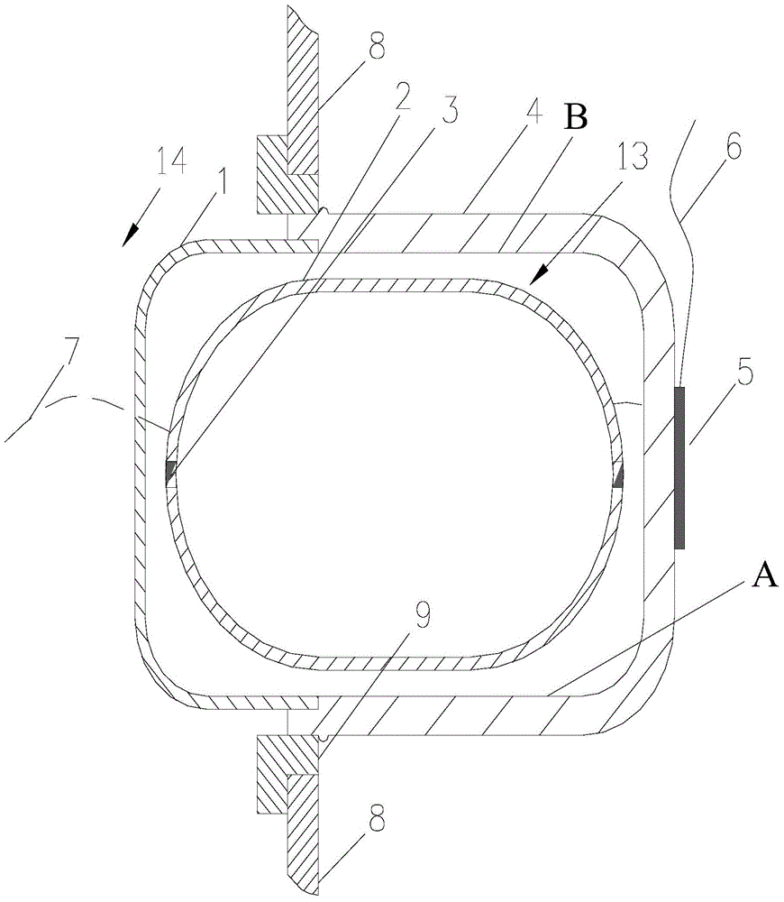
[0046] The inside of the compressor housing 8 is provided with an oil storage cavity 14 for refrigeration lubricating oil, such as figure 1 As shown, the compressor shell 8 is provided with an opening, and the liquid level sensor is installed at the opening, and the liquid level sensor detects the change of the liquid level of the refrigerated lubricating oil in the oil storage chamber 14 .
[0047] In this embodiment, the liquid level sensor includes a housing 4 , a filter 1 , a float 2 and an inductor 5 .
[0048] The housing 4 of the liquid level sensor has an opening, and the opening of the housing 4 is in sealing connection with the opening of the compressor housing 8 . In this embodiment, the shell 4 protrudes outward relative to the compressor shell 8, and the liquid level sensor does not occupy the internal space of the compressor, which is especially suitable for small semi-hermetic and hermetic compressors.
[0049] The housing 4 may be welded or screwed to the open...
Embodiment 2
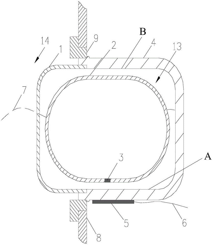
[0069] refer to figure 2 The difference between this embodiment and Embodiment 1 is that a permanent magnet 3 is provided on the floating ball 2, and the permanent magnet 3 is embedded in the middle position below the floating ball 2, and the quality of the permanent magnet 3 makes the center of gravity of the floating ball 2 offset, thereby Stable on the bottom, the sensor 5 is installed on the lower outer wall of the housing 4 .
Embodiment 3
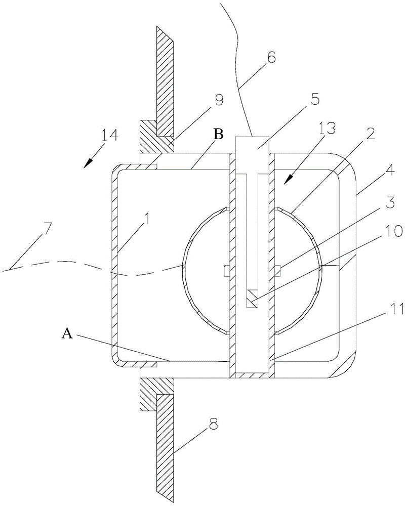
[0071] refer to image 3 The difference between this embodiment and Embodiment 1 is that the liquid level sensor further includes a hollow guide tube 11 , and the guide tube 11 extends from the housing 4 of the liquid level sensor to the detection cavity 13 . At least one end of the guide tube 11 is provided with an opening, through which the hollow inner space of the guide tube 11 communicates with the external environment, but is isolated from the detection cavity 13 . The guide tube 11 can also pass through the housing 4 or not. In this embodiment, both ends of the guide tube 11 are airtightly and fixedly connected to the housing 4 , and one end is provided with an opening. The guide tube 11 can be a hollow tube provided separately, or a hollow tube extending from the housing 4 , and the other end can be connected to the housing 4 or not. The guide tube 11 may be a circular hollow tube, a square hollow tube, etc., which are not limited in the present invention. The induct...
PUM
| Property | Measurement | Unit |
|---|---|---|
| Wall thickness | aaaaa | aaaaa |
| Density | aaaaa | aaaaa |
| Density | aaaaa | aaaaa |
Abstract
Description
Claims
Application Information