Optical waveguide chip coupling testing clamp
A technology for testing fixtures and optical waveguides, applied in the field of optical waveguides, can solve the problems of single fixture chip fixing method, lack of adjustment function, limited application range, etc., and achieve flexible chip attitude adjustment, optimized coupling adjustment effect, and wide application range Effect
- Summary
- Abstract
- Description
- Claims
- Application Information
AI Technical Summary
Problems solved by technology
Method used
Image
Examples
example 1
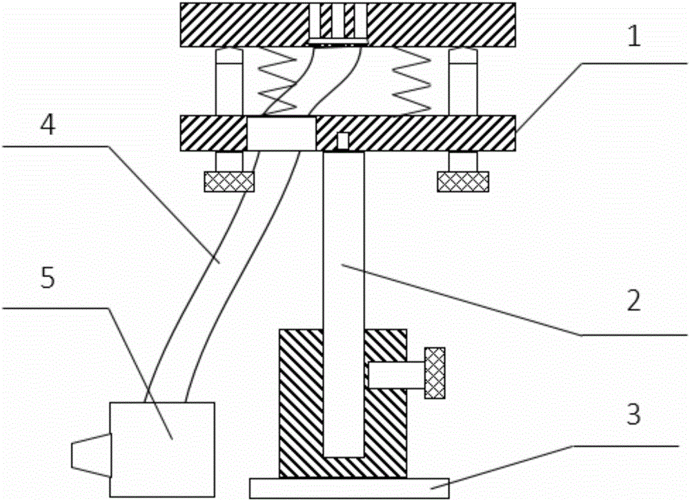
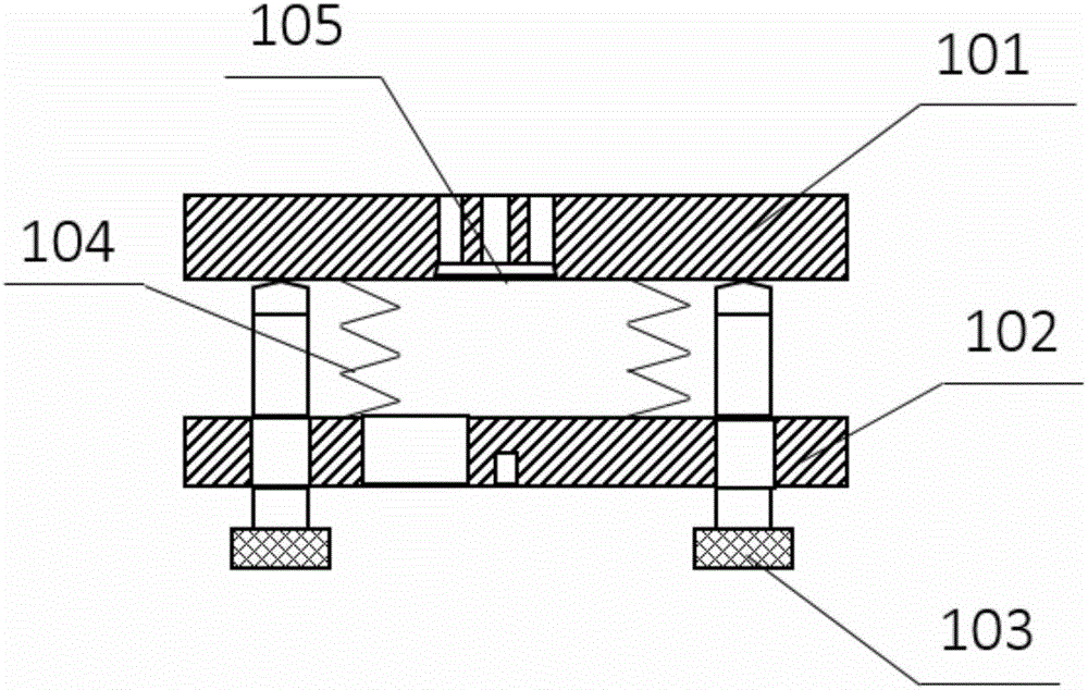
[0039] Aluminum alloy is selected as the manufacturing material of the film holder, stainless steel is selected as the manufacturing material of the support rod and the support seat, rubber is used to make the air guide hose, and standard parts such as the height adjustment screw and the inclination angle adjustment screw are selected.
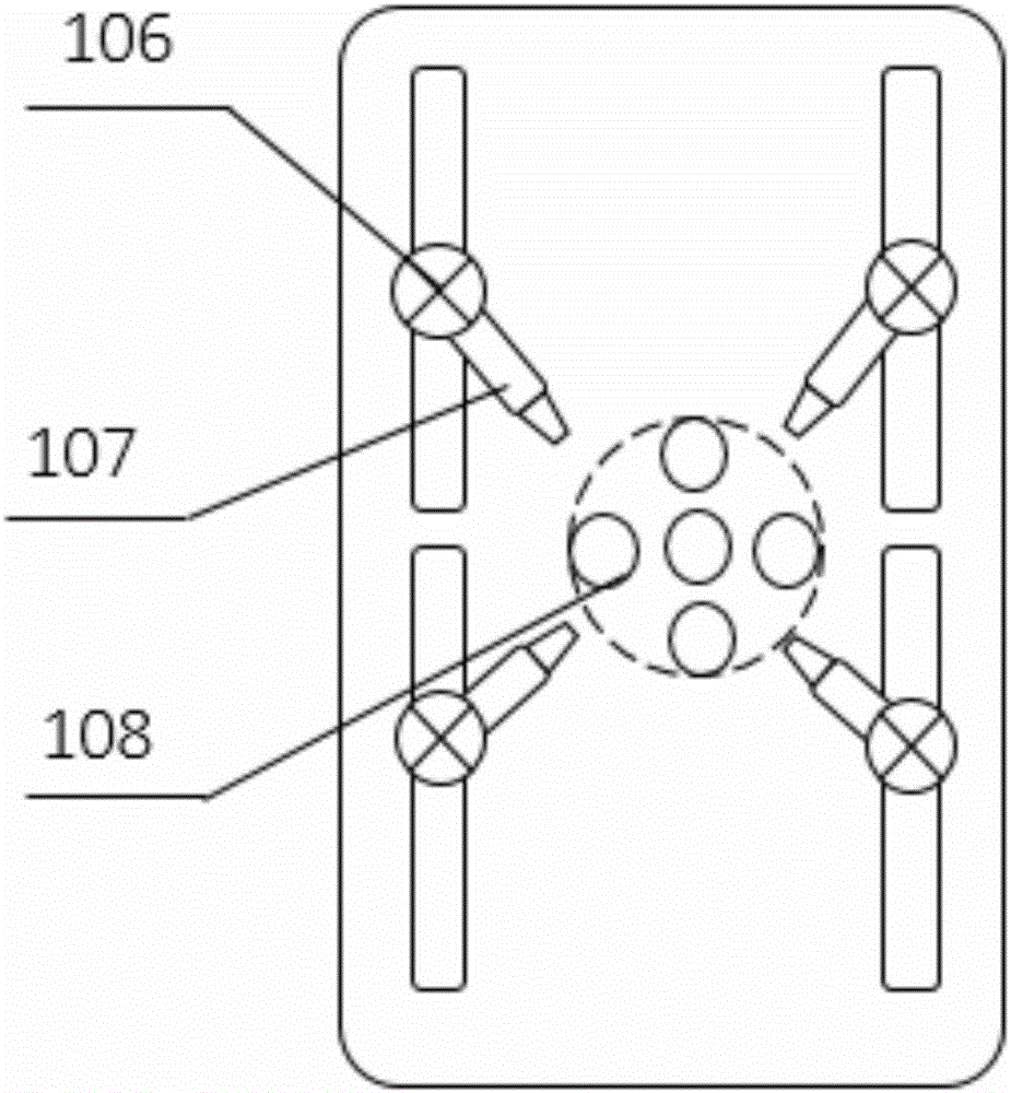
[0040] The film holder is designed to be 8cm in length, 4cm in width, and 3cm in height, the aperture of the suction piece is 3mm, and the entire area of the suction piece is 1cm 2 , the support rod is 12cm long, the entire optical waveguide chip coupling test fixture can be adjusted in height from 16 to 21cm, and the tilt and pitch adjustment angle of the wafer stage is -5° to 5°.
[0041] The optical waveguide chip coupling test fixture shown in the above example can be used for clamping the optical waveguide chip and adjusting the chip height and tilt angle in the optical fiber optical waveguide chip coupling test.
PUM
 Abstract
Description
Claims
Application Information
 - R&D
- Intellectual Property
- Life Sciences
- Materials
- Tech Scout
- Unparalleled Data Quality
- Higher Quality Content
- 60% Fewer Hallucinations
Browse by: Latest US Patents, China's latest patents, Technical Efficacy Thesaurus, Application Domain, Technology Topic, Popular Technical Reports.
© 2025 PatSnap. All rights reserved.Legal|Privacy policy|Modern Slavery Act Transparency Statement|Sitemap|About US| Contact US: help@patsnap.com


