
High-precision high-rigidity space camera filter switching mechanism

A filter switching and space camera technology, which is applied to the camera body, camera, optics, etc., can solve the problems of low position repeatability, difficult installation process, and affecting imaging quality, so as to improve rigidity and anti-vibration Good performance, the effect of improving position repeatability accuracy

Active Publication Date: 2015-11-18
BEIJING RES INST OF SPATIAL MECHANICAL & ELECTRICAL TECH
View PDF5 Cites 15 Cited by
  • Summary
  • Abstract
  • Description
  • Claims
  • Application Information

AI Technical Summary

Problems solved by technology

The structure of the existing switching mechanism is that the bearing is built-in, and the filter wheel mounting plate is installed on the central shaft through the bearing group. The bearing group is a pair of angular contact ball bearings, which are symmetrically used as the central support. The cantilever configuration has a relatively high overall rigidity. Low, large vibration response
In addition, the bearings in the prior art are not integrated designs. Due to the limitation of machining accuracy, the coaxial installation process of the two bearings is difficult, and slight shaking occurs during the rotation process, resulting in inconsistent positions of different filters after switching into the optical path, and position repeatability. Not high, affecting image quality

Method used


Image

  • High-precision high-rigidity space camera filter switching mechanism
  • High-precision high-rigidity space camera filter switching mechanism
  • High-precision high-rigidity space camera filter switching mechanism

Examples


Embodiment Construction

[0022] Below in conjunction with accompanying drawing and specific embodiment the present invention is described in further detail:

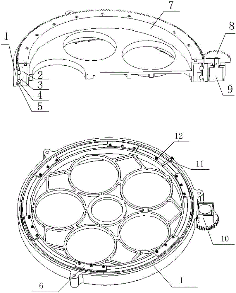
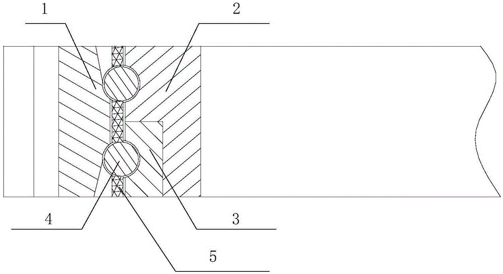
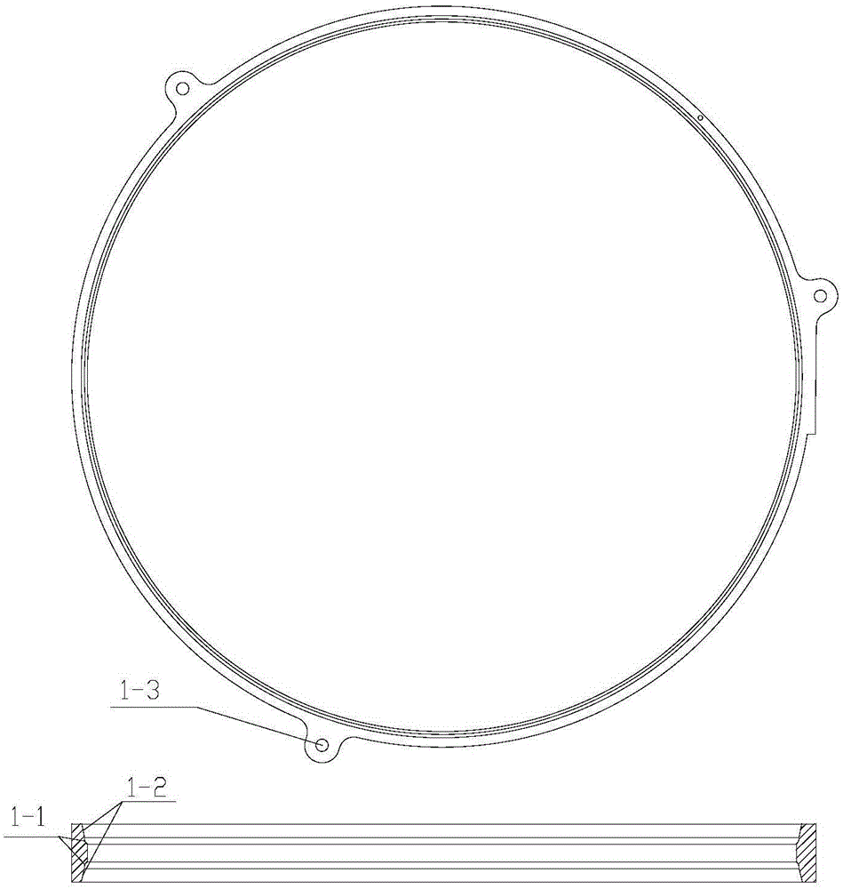
[0023] Such as figure 1 Shown is a schematic diagram of the composition of the high-precision and high-rigidity space camera filter switching mechanism of the present invention. As shown in the figure, it includes an integrated bearing, a gear pair, and a drive control part; the integrated bearing is external, the integrated bearing is outside, and the optical filter The mounting plate 7 is concentrically installed in the integrated bearing, and the drive control part is installed on the integrated bearing. The integrated bearing includes an integrated outer collar 1, an inner collar 2, an embedded ring 3, a ball 4, a ball cage 5 and a pressure block 6. This configuration integrates the switching mechanism with the external mounting interface and two bearings Design, reduce the number of structural parts and installation errors between structur...


PUM


Abstract

The invention relates to a high-precision high-rigidity space camera filter switching mechanism, and the mechanism is used for enabling space camera filters to enter into an optical path sequentially. The mechanism consists of an integrated bearing part, a gear pair, and a drive control assembly. The integrated bearing part comprises an integrated bearing outer ring, an inner shaft ring, an embedded ring, a ball, a ball holder, and a pressure block. The gear pair consists of a filter installation disc and a small gear, and is connected with the inner shaft ring of an integrated bearing part. A driving part comprises a motor, a motor installation frame, a magnetic steel, and a Hall sensor. The motor drives the small gear to drive the filter installation disc to rotate under a control instruction. According to the invention, the mechanism employs a mode that the bearing is disposed outside and the filter installation disc is disposed inside, and increases the rigidity. The mechanism employs the integrated design of the bearing, is high in rotation precision, is excellent in axial bearing performance, and is low in assembly difficulty. The mechanism employs a stress relief design of the filter installation disc, reduces the installation stress and thermal deformation under a low-temperature working condition.

Description

technical field [0001] The invention relates to a method for switching filters of different spectral bands into an optical path during imaging of a space camera to realize detection of different optical spectral bands. , especially a high-precision and high-rigidity space camera filter switching mechanism. Background technique [0002] For spatial multi-spectral cameras to perform multiple spectral band cyclic imaging, it is necessary to sequentially switch filters that can pass through different spectral bands into the optical path. The structure of the existing switching mechanism is that the bearing is built-in, and the filter wheel mounting plate is installed on the central shaft through the bearing group. The bearing group is a pair of angular contact ball bearings, which are symmetrically used as the central support. The cantilever configuration has a relatively high overall rigidity. Low, large vibration response. In addition, the bearings in the prior art are not i...

Claims


Application Information

Patent Timeline
Patent Type & Authority Applications(China)
IPC IPC(8): G03B17/14G02B7/00
Inventor 宫辉陈伟周峰
Owner BEIJING RES INST OF SPATIAL MECHANICAL & ELECTRICAL TECH
Learn More