Positioning structure for PCB and upper insulation support

A technology of insulating support and positioning structure, which is applied to the shape/style/structure, structural connection, casing/cover/support of winding conductors, etc., can solve problems such as easy occurrence of defective products and difficult automation, and improve production efficiency. , the effect of ensuring accuracy and simplifying the structure

Active Publication Date: 2015-11-18
BERGSTROM CHINA GRP
View PDF8 Cites 15 Cited by
  • Summary
  • Abstract
  • Description
  • Claims
  • Application Information

AI Technical Summary

Problems solved by technology

[0005] In the production process of the existing brushless motor, one is to fix the PCB board on the housing first, and then assemble the PCB board and the upper insulating bracket through the terminal connection holes on the PCB board and the terminals on the upper insulating bracket. At the same time, in the actual production of this assembly method, due to the large error in the relative position between the terminal connection hole on the PCB board and the terminal on the upper insulating bracket, defective products are prone to appear in the automated production process; another It is to install the PCB board on the upper insulating bracket first, and then directly weld the wires of the stator winding to the PCB board. In actual production, this assembly method needs to manually solder the wires of the stator winding to the PCB board. Therefore, it is difficult Automate

Method used


Image

  • Positioning structure for PCB and upper insulation support
  • Positioning structure for PCB and upper insulation support
  • Positioning structure for PCB and upper insulation support

Examples


Embodiment 1

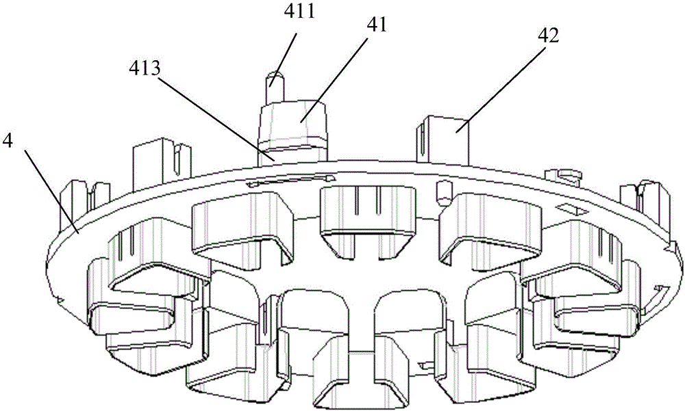
[0038] The embodiment of the present invention provides a positioning structure for a PCB board and an upper insulating bracket, which is suitable for brushless motors, see figure 1 , the positioning structure includes: an upper insulating bracket 4 .

[0039] The upper surface of the upper insulating support 4 is evenly provided with a plurality of positioning platforms 41 along the circumferential direction, and the top surface of the positioning platforms 41 is higher than the top surface of the terminal fixing seat 42 arranged on the upper surface of the upper insulating support 4. h, h is greater than zero, The terminal fixing seat 42 is used for inserting an insulation displacement connection (Insulation Displacement Connection, “IDC” for short) terminal (not marked in the drawings).

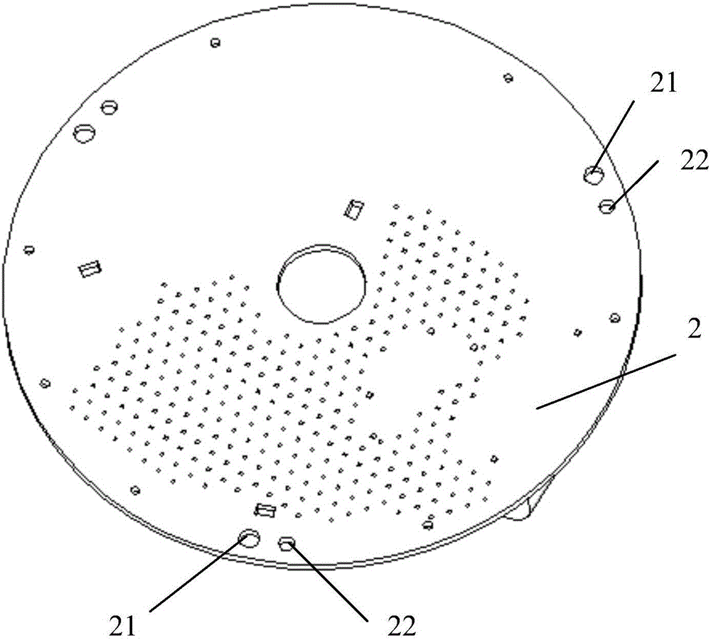
[0040] The top surface of each positioning platform 41 is provided with a guide positioning column 411, and one end where the guiding positioning column 411 cooperates with the PCB board 2...

Embodiment 2

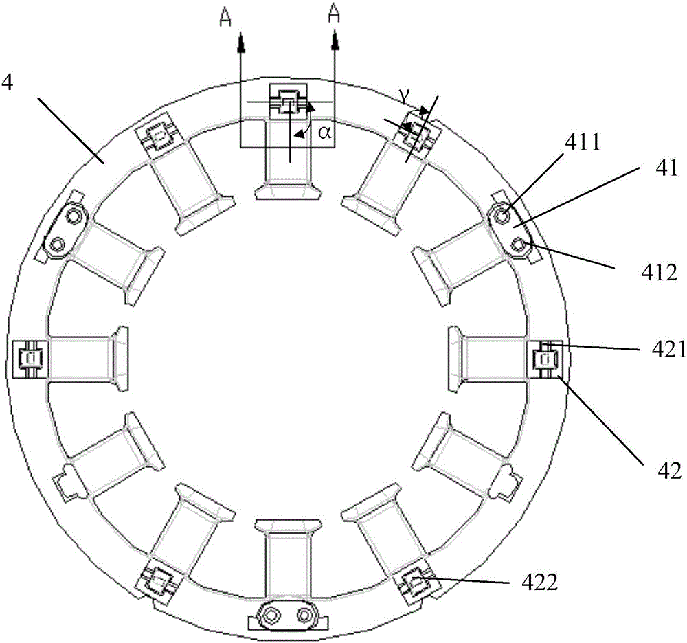
[0051] The embodiment of the present invention provides a positioning structure for a PCB board and an upper insulating bracket, which is suitable for brushless motors, see Figure 4 , the positioning structure includes: an upper insulating bracket 4 .

[0052] The upper surface of the upper insulating support 4 is evenly provided with a plurality of positioning platforms 41 along the circumferential direction, and the top surface of the positioning platforms 41 is higher than the top surface of the terminal fixing seat 42 arranged on the upper surface of the upper insulating support 4. h, h is greater than zero, The terminal fixing base 42 is used for inserting IDC terminals.

[0053] The top surface of each positioning platform 41 is provided with a guide positioning column 411, and one end where the guiding positioning column 411 cooperates with the PCB board 2 is a tapered structure; There is a wire slot 413 for limiting wires.

[0054] see Figure 5 , the top surface o...

Embodiment 3

[0081] An embodiment of the present invention provides a positioning structure for a PCB board and an upper insulating bracket. In practical applications, the upper insulating bracket in the positioning structure can form a stator with an insulating bracket with other structures. See Figure 8 , the stator with an insulating support includes: a stator core 5, an upper insulating support 4 and a lower insulating support 7 are respectively inserted on the upper and lower end surfaces of the stator iron core 5, and a plurality of terminals are arranged on the upper surface of the upper insulating support 4 The fixing seat 42 and a plurality of wire passing seats 46 are provided on the lower surface of the lower insulating support 7 with a plurality of wire passing seats 46 .

[0082] see Figure 9 and Figure 10 , the upper slot insulation 43 on the upper insulating bracket 4, the winding teeth (not marked in the drawings) on the stator core 5 and the lower slot insulation 73 on...


PUM


Abstract

The invention discloses a positioning structure for a PCB and an upper insulation support, and belongs to the technical field of brushless motors. The positioning structure comprises the PCB and the upper insulation support, the upper surface of the upper insulation support is provided with a plurality of positioning benches, the top surfaces of the positioning benches are h higher than the top surfaces of terminal fixing seats, the top surface of each positioning bench is provided with a guide positioning column matched with a positioning hole and a fixing hole matched with an installing hole, one end of the guide positioning column, matched with the positioning hole, is a tapered structure, and a sidewall of each positioning bench is provided with a wire-passing groove for limiting a conducting wire. According to the positioning structure, in the assembling process of the PCB and the upper insulation support, the guide positioning column and the positioning holes are matched so that accurate positioning between terminals of the upper insulation support and terminal connection holes of the PCB can be realized, the quantity of defective products in the automatic generation can be reduced, and the yield is increased.

Description

technical field [0001] The invention relates to the technical field of brushless motors, in particular to a positioning structure for a PCB board and an upper insulating support. Background technique [0002] A brushless motor is a motor without brushes and commutators (or collector rings), which operates by changing the alternating frequency and waveform of the current wave that passes into its stator winding coil. Brushless motors are widely used by major manufacturers because of their high efficiency, low energy consumption, low noise, long life, high reliability, servo control, stepless frequency conversion speed regulation, relatively low cost and ease of use. [0003] The existing brushless motor mainly includes: a housing, a printed circuit board ("PCB" for short), a rotor, and a stator. The stator includes: an upper insulating support, a stator core, a lower insulating support, and a stator winding. The upper insulating bracket and the lower insulating bracket are r...

Claims


Application Information

Patent Timeline
Patent Type & Authority Applications(China)
IPC IPC(8): H02K11/00
CPCH02K3/522H02K2211/03H02K2213/03H02K11/33H02K2203/12H02K5/225H02K3/28H02K3/525H02K2203/03
Inventor 李更祥王磊杨奎林
Owner BERGSTROM CHINA GRP
Why Eureka
Try Eureka