
Overcurrent protection method of PMSM driver

A permanent magnet synchronous motor, overcurrent protection technology, applied in emergency protection circuit devices, electronic commutation motor control, single motor speed/torque control, etc. capacity and other issues, to achieve high reliability, simple algorithm implementation, and eliminate the effect of voltage pumping

Active Publication Date: 2015-11-18
哈尔滨深能电机有限公司
View PDF3 Cites 1 Cited by
  • Summary
  • Abstract
  • Description
  • Claims
  • Application Information

AI Technical Summary

Problems solved by technology

[0004] The purpose of the present invention is to provide an overcurrent protection method for a permanent magnet synchronous motor driver, in order to solve the problem that the existing overcurrent protection method for the driver can only protect the safety of the permanent magnet The problem of protecting the driver with small bus capacitor capacity

Method used


Image

  • Overcurrent protection method of PMSM driver
  • Overcurrent protection method of PMSM driver
  • Overcurrent protection method of PMSM driver

Examples


specific Embodiment approach 1

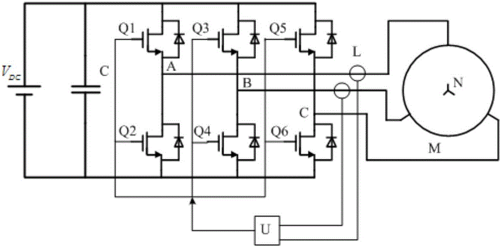
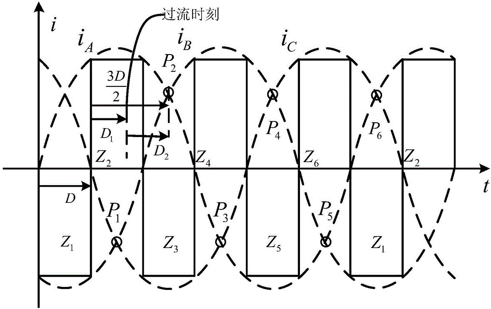
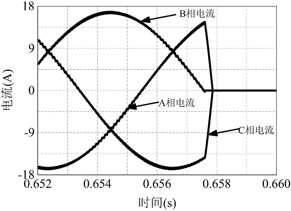
[0024] Specific implementation mode one: combine figure 1 , figure 2 , image 3 , Figure 4 , Figure 5 , Figure 6 As shown, its method steps are:

[0025] Step 1: When the permanent magnet synchronous motor M is running normally, the microcontroller U detects and records the time when any two phase currents are adjacent to the zero crossing point through its internal counter in real time, and this time is denoted by D; the starting time of timing is a certain phase At the zero crossing point of the current, the counter is cleared to zero at the next phase current zero crossing point, and the timing is restarted;

[0026] Step 2: When the permanent magnet synchronous motor M has an overcurrent or needs to be shut down in an emergency, the microcontroller U detects the current status of the three phases A, B, and C through the current sensor L, and controls the switch tubes Q1, Q2, Q3, Q4, The switching states of Q5 and Q6, namely:

[0027] When the A-phase current is ...


PUM


Abstract

The invention provides an overcurrent protection method of a PMSM driver, and belongs to the technical field of motor equipment. The method comprises the steps that 1) when a PMSM M operates normally, a microcontroller U uses an internal counter to detect and record time D between adjacent zero-crossing points of any two phases of currents in real time; 2) when overcurrent or other emergency state occurs in the PMSM M and the PMSM needs shutdown, the microcontroller U uses a current sensor L to detect current states of phases A, B and C, and control ON / OFF states of switch tubes Q1 to Q6; and 3) the connected switch tubes are switched off at time D2 from the moment that overcurrent or other emergency state occurs in the PMSM M and the PMSM needs shutdown, D2=3D / 2-D1, and thus, overcurrent protection for the motor driver is realized. Thus, voltage pumping-up of a bus capacitor of the motor driver can be substantially reduced, lower than 10% of the original, and even eliminated, and the safety of the driver can be protected in emergency states as overcurrent.

Description

technical field [0001] The invention belongs to the technical field of electrical equipment. Background technique [0002] Due to the high power density and excellent control characteristics of permanent magnet synchronous motors, they are widely used in transportation, aerospace, household appliances and other fields. However, permanent magnet synchronous motors require dedicated drives for control. Currently commonly used drivers generally adopt an AC-DC-AC main circuit design scheme or a DC-AC design scheme directly powered by a DC source. No matter what design scheme is adopted, it is necessary to add a large-capacity electrolytic capacitor to the DC bus of the driver to suppress voltage fluctuations. Although electrolytic capacitors have the advantages of cheap price and high energy density, they have poor stability, low life, are easily affected by external temperature, and are prone to generate inrush current during power-on. Reducing the use of electrolytic capaci...

Claims


Application Information

Patent Timeline
Patent Type & Authority Applications(China)
IPC IPC(8): H02P6/00H02P6/08H02H7/08
Inventor 徐永向黄盈亮邹继斌王宝超刘剑胡建辉尚静王骞刘承军
Owner 哈尔滨深能电机有限公司
Learn More