Metal filing removal mechanism for production process of minced fillet
A technology of production process and metal shavings, which is applied in the field of metal shavings removal mechanism, can solve the problems of low qualified rate of finished products and low removal efficiency, and achieve the effect of high degree of automation, high removal efficiency and high pass rate
- Summary
- Abstract
- Description
- Claims
- Application Information
AI Technical Summary
Problems solved by technology
Method used
Image

Examples
Embodiment 1
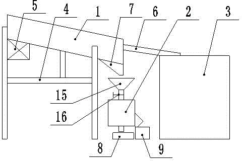
[0020] Embodiment one: combined with attached figure 1 , a mechanism for removing metal shavings in the surimi production process, including a transfer tank 1, a metal separator 2, a storage box 3 and a support 4, the transfer tank 1 is a downwardly inclined structure from left to right, the transfer tank 1 and the support 4-phase matching, the bottom of the transfer tank 1 is provided with a vibrator 5, the middle and upper part of the right side of the transfer tank 1 is provided with an inclined discharge plate 6 compatible with the storage box 3, and the bottom of the transfer tank 1 is provided with a There is a conical bucket 7 suitable for the metal separator 2, and the metal separator 2 draws the minced fish feed box 8 and the metal feed box 9 respectively.
Embodiment 2
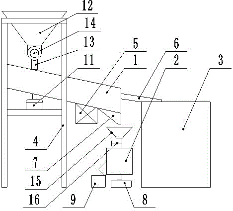
[0021] Embodiment two: combined with attached figure 2 , a metal chip removal mechanism in the surimi production process, including a transfer tank 1, a metal separator 2, a storage box 3 and a support 4, the support 4 is provided with a feed hopper 12, and the bottom of the feed hopper 12 is provided with a The drop tube 13 on the left side of the transfer tank 1 is matched, and the lower part of the feed hopper 12 is provided with a feeder 14 that is compatible with the drop tube 13. The transfer tank 1 is a downwardly inclined structure from left to right. The transfer tank 1 is compatible with the support 4, the right side of the transfer tank 1 bottom is provided with a vibrator 5, the left side of the transfer tank 1 bottom is provided with an agitator 11, and the middle and upper part of the transfer tank 1 right side is provided with a material storage device. The inclined discharge plate 6 suitable for the box 3, the bottom of the right side of the transfer tank 1 is...
Embodiment 3
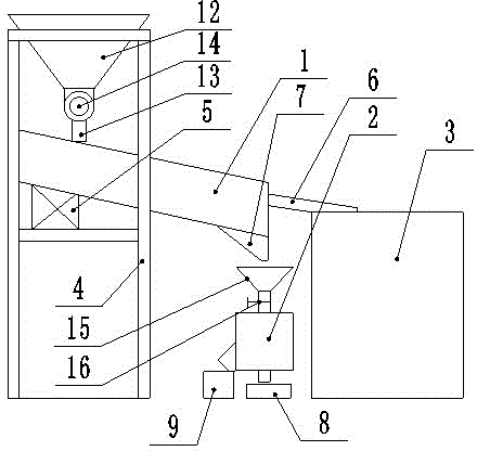
[0022] Embodiment three: combined with attached image 3 and 4 , a metal chip removal mechanism in the surimi production process, including a transfer tank 1, a metal separator 2, a storage box 3 and a support 4, the support 4 is provided with a feed hopper 12, and the bottom of the feed hopper 12 is provided with a The drop tube 13 on the left side of the transfer tank 1 is matched, and the lower part of the feed hopper 12 is provided with a feeder 14 that is compatible with the drop tube 13. The transfer tank 1 is a downwardly inclined structure from left to right. The transfer tank 1 is compatible with the support 4, the left side of the transfer tank 1 bottom is provided with a rapper 5, the inside of the transfer tank 1 right side is provided with a plurality of elastic sheets 10, and the middle and upper part of the transfer tank 1 right side is provided with a The inclined discharge plate 6 that is compatible with the storage box 3, the bottom of the right side of the ...
PUM
 Abstract
Description
Claims
Application Information
PatSnap Eureka turns technology decisions into work you can execute. Powered by our Innovation Knowledge Graph, it runs expert workflows across engineering, life sciences, materials and intellectual property. Get your review-ready output in minutes.


