Self-lubrication impact crusher

An impact crusher, automatic lubrication technology, applied in the field of machinery and equipment, can solve the problems of reduced grease lubrication ability, accelerated bearing wear, increased noise, etc., to reduce equipment wear and noise, improve equipment life, and good lubrication performance. Effect

Inactive Publication Date: 2015-11-25
NANTONG ZHENQIANG MACHINERY MFG
View PDF8 Cites 0 Cited by
  • Summary
  • Abstract
  • Description
  • Claims
  • Application Information

AI Technical Summary

Problems solved by technology

However, during the high-speed rotation of the main shaft of the impact crusher, due to the high heat caused by friction, the lubricating ability of the grease will decrease, the bearing wear will accelerate, the noise will increase, and the life of the equipment will be shortened.

Method used


Image

  • Self-lubrication impact crusher
  • Self-lubrication impact crusher

Examples


Embodiment Construction

[0008] The present invention will be further described below in conjunction with the drawings and specific embodiments.

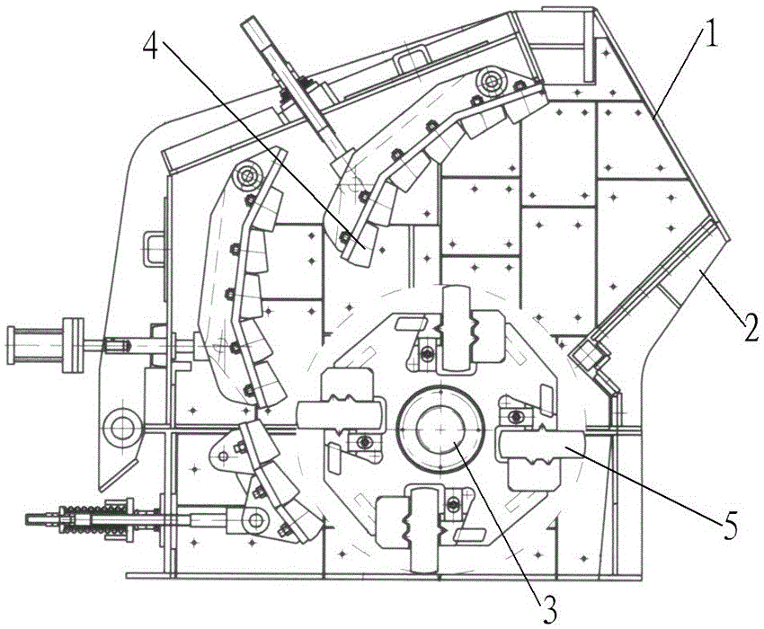
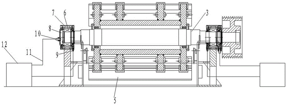
[0009] figure 1 , figure 2 Middle: feed inlet 1, machine casing 2, main shaft 3, counterattack device 4, blower 5, bearing 6, bearing seat 7, end cover 8, oil inlet 9, oil outlet 10, oil pipe 11, thin oil station 12.

[0010] The automatic lubrication type impact crusher includes a casing 2, a main shaft 3, and a counter-attack device 4 provided with a feed port 1. The main shaft 3 and the counter-attack device 4 are placed inside the casing 2, and the cylinder of the main shaft 3 A hammer 5 is fixedly connected to the surface. The two ends of the main shaft 3 and the side wall of the casing 2 are movably connected through a bearing 6, and a bearing seat 7 is connected to the outer ring of the bearing 6. The end of the bearing 6 is sealed by an end cover 8. The bearing 6 is placed in the lubrication space enclosed by the bearing seat 7 and the end cover 8. Th...


PUM


Abstract

The invention discloses a self-lubrication impact crusher. The self-lubrication impact crusher comprises a main case with a feed opening, a main shaft and an impact device, wherein the main shaft and the impact device are arranged in the main case; the cylindrical surface of the main shaft is fixedly connected with a plate hammer; the two ends of the main shaft are movably connected with the side wall of the main case through bearings; the bearings are placed in lubrication spaces formed by bearing pedestals and end covers in an enclosing manner; and each end cover is provided with an oil inlet nozzle and an oil outlet nozzle. The self-lubrication impact crusher has the beneficial effects that the main shaft maintains favorable lubrication performance under the condition of high-speed rotation, so that equipment abrasion and noise are reduced and the equipment service life is prolonged.

Description

Technical field [0001] The invention relates to mechanical equipment, in particular to an automatic lubrication type impact crusher. Background technique [0002] The impact crusher is a crushing machine that uses impact energy to crush materials. The working principle of this machine is driven by the motor, the rotor rotates at a high speed. When the material enters the impact area of ​​the blower, it collides with the blower on the rotor to be broken, and then is thrown to the counterattack device to break again, and then from the counterattack liner. Bounce back to the hammer action area and break again. This process is repeated. The material enters the first, second, and third counterattack chamber from large to small, and is repeatedly crushed until the material is crushed to the required particle size and discharged from the discharge port. According to the production requirements, the speed is increased to improve the crushing efficiency. In the known technology, the lub...

Claims


Application Information

Patent Timeline
Patent Type & Authority Applications(China)
IPC IPC(8): B02C13/09B02C13/26
Inventor 袁传安杨银生
Owner NANTONG ZHENQIANG MACHINERY MFG
Why Eureka
Try Eureka