
Robot grinding system for outer surface of cylinder with boss

A technology of outer surface and robot, which is applied in the field of metal product processing, can solve the problems of low operation tasks, long processing time, grinding and processing troubles, etc., and achieve the effect of reducing labor intensity, improving production efficiency, and ensuring consistency

Inactive Publication Date: 2015-11-25
DONGGUAN ZHAOKE HARDWARE IND CO LTD
View PDF6 Cites 40 Cited by
  • Summary
  • Abstract
  • Description
  • Claims
  • Application Information

AI Technical Summary

Problems solved by technology

[0002] At present, the grinding and polishing operation of parts on the outer surface of a cylinder with convex parts (such as bosses) is basically done by hand-held tools and relying on experience. The high cost restricts the development of large-scale pipe fitting processing technology
In particular, the current manual work is difficult to ensure the consistency of quality and processing efficiency. The processing takes a long time, heavy work tasks and low efficiency seriously affect the development cycle of some equipment, and workers are easily injured during work.
However, if the machine is used for automatic grinding, the current grinding machine will not automatically avoid when it encounters a raised part on the surface of the workpiece, which will cause great trouble to the grinding process.
Therefore, the grinding process of the outer surface of large cylinders with bosses is a weak link in manufacturing and has become a bottleneck restricting the development of large cylindrical pipe fittings manufacturing industry

Method used


Image

  • Robot grinding system for outer surface of cylinder with boss
  • Robot grinding system for outer surface of cylinder with boss
  • Robot grinding system for outer surface of cylinder with boss

Examples


Embodiment Construction

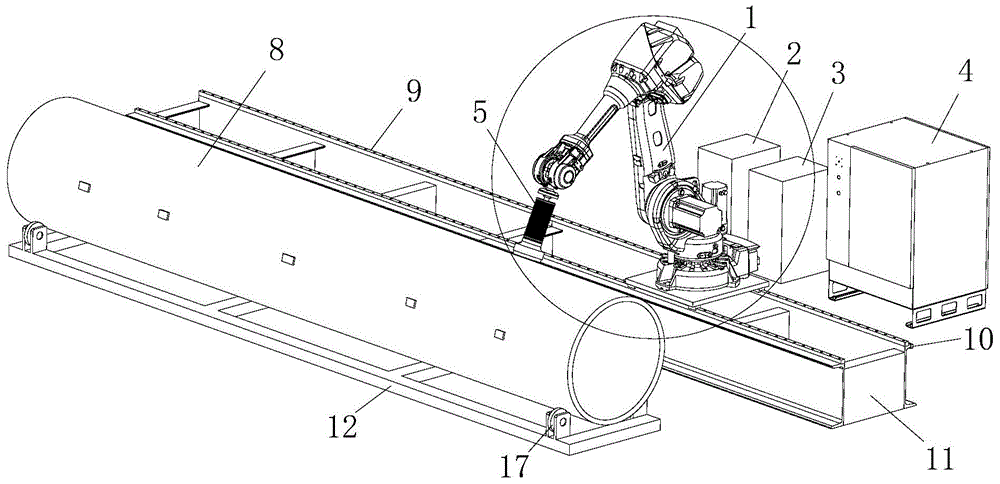
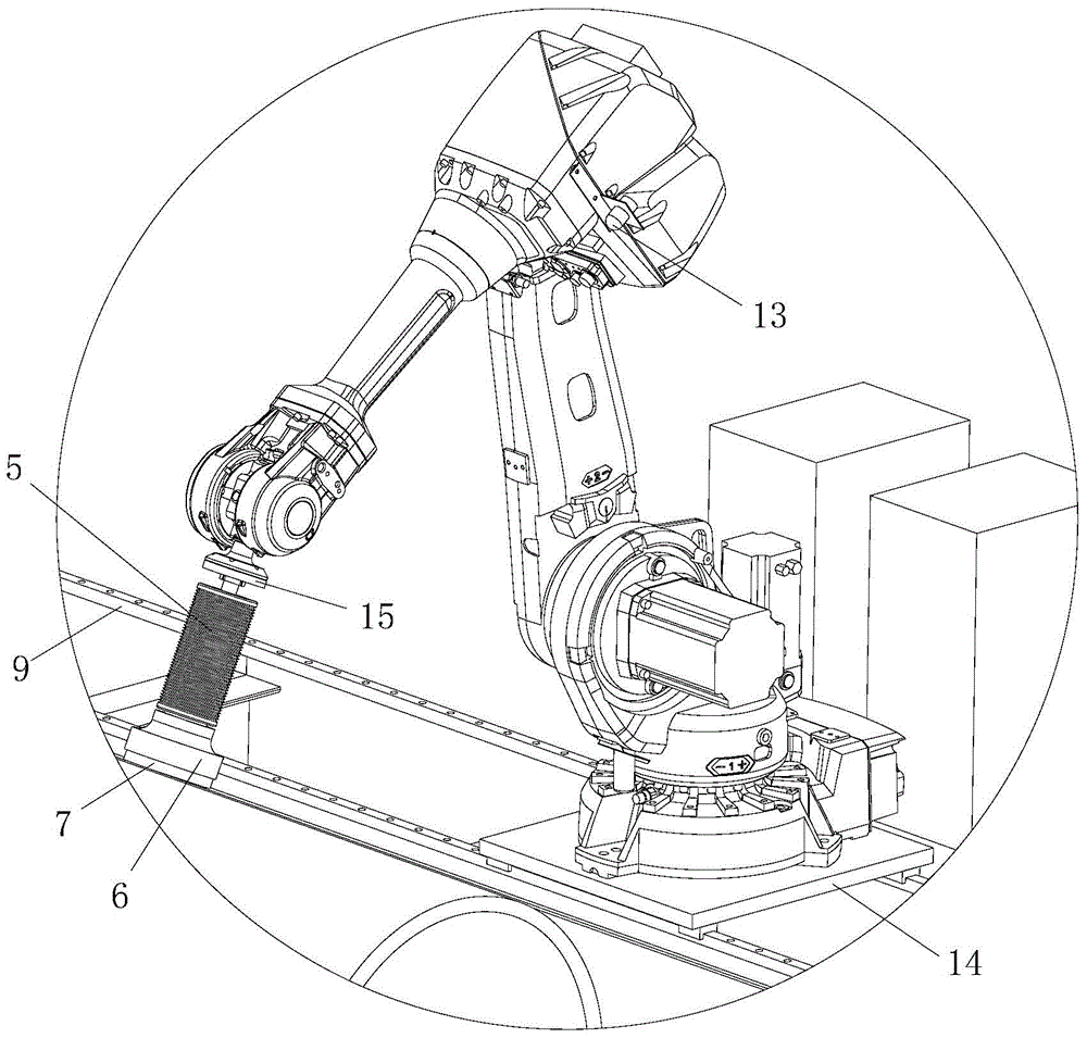
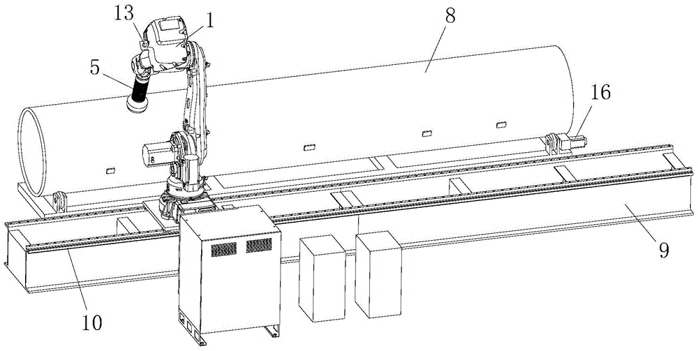
[0025] In this example, refer to figure 1 , figure 2 and image 3 , the robot grinding system for the outer surface of a cylinder with a boss includes,

[0026] Mobile track 11, is used for installing industrial robot 1;

[0027] The industrial robot 1 is installed on the moving track 11, and the forearm part of the industrial robot 1 is stretched to align with the workpiece 8 to be processed;

[0028] Robot control cabinet 2, connecting and controlling industrial robot 1;

[0029] The barostat 5 and the pneumatic control cabinet 3, the barostat 5 is installed on the front end of the forearm of the industrial robot 1, the pneumatic control cabinet 3 is connected to the barostat 5, and the pressure of the barostat 5 is controlled by a pneumatic circuit;

[0030] The electrical system control cabinet 4 is connected to the robot control cabinet 2 and the pneumatic control cabinet 3, and is used for offline calculation of the kinematics and dynamics of the industrial robot 1,...


PUM


Abstract

The invention discloses a robot grinding system for the outer surface of a cylinder with a boss. The robot grinding system comprises a movable rail, an industrial robot, a robot control cabinet, a barostata, a pneumatic control cabinet, an electric system control cabinet, a grinding tool and a visual camera. The industrial robot is arranged on the movable rail. The barostata is fixed to a front arm of the industrial robot. The grinding tool is installed at the front end of the barostata. The visual camera is installed on the industrial robot, connected with the robot cabinet and used for monitoring the position of the boss on the surface of the workpiece. The barostata enables a grinding wheel to press the machined surface with the constant pressure all the time, and meanwhile the industrial robot enables the grinding pressure to be in the normal direction of the machined surface. When encountering a protruding part, the visual camera immediately feeds the information back to the industrial robot to avoid the protruding part. The consistency of the grinding accuracy and quality of the outer surface of the cylinder workpiece with the boss can be effectively guaranteed, the production efficiency is improved, safety is improved, and labor intensity of workers is relieved.

Description

technical field [0001] The invention relates to the technical field of metal product processing, in particular to a device for grinding the outer surface of a cylinder with a raised part (such as a boss). Background technique [0002] At present, the grinding and polishing operations of parts on the outer surface of a cylinder with raised parts (such as bosses) are basically done by hand-held tools and relying on experience. The high cost restricts the development of large-scale pipe fitting processing technology. In particular, the current manual operation is difficult to ensure the consistency of quality and processing efficiency. The processing takes a long time, heavy work tasks and low efficiency seriously affect the development cycle of some equipment, and workers are easily injured during work. And if adopt machine automatic grinding, current grinding machine can not avoid automatically when running into the protruding part of workpiece surface, causes very big puzzl...

Claims


Application Information

Patent Timeline
IPC IPC(8): B24B5/04B24B5/35B24B27/00
CPCB24B5/04B24B5/35B24B27/0007
Inventor 张新桥谢月明梁文星
Owner DONGGUAN ZHAOKE HARDWARE IND CO LTD
Learn More