A kind of cbn cutting grinding wheel of resin bond and its manufacturing process
A production process and bonding agent technology, applied in the direction of bonding grinding wheels, manufacturing tools, abrasives, etc., can solve the problems of low life and low durability of grinding wheels, and achieve improved life and durability, high grinding efficiency, and high hardness. Effect
- Summary
- Abstract
- Description
- Claims
- Application Information
AI Technical Summary
Problems solved by technology
Method used
Image
Examples
Embodiment 1
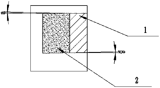
[0029] refer to Figure 1~2 As shown, a resin-bonded CBN cut-in grinding wheel includes a substrate 1 and an abrasive layer 2, the angle between the upper surface of the abrasive layer 2 and the upper surface of the substrate 1 is α, 1°≤α≤3°, and the abrasive The angle between the lower surface of the layer 2 and the lower surface of the substrate 1 is β, 1°≤β≤3°.
[0030] The abrasive layer is made of the following raw materials in parts by weight: resin bond 10-25, carbonyl iron powder 30-40, CBN abrasive 42-62, magnesium oxide 3-5 and wetting agent 1-5.
[0031] The CBN of described resin bond cuts into the manufacturing process of grinding wheel, comprises the steps:
[0032] (1) After weighing the raw materials in proportion, firstly stir and grind the CBN abrasive and wetting agent evenly to make the CBN abrasive fully wet; then add resin binder, carbonyl iron powder and magnesium oxide to fully stir and mix evenly;
[0033] (2) Molding: heat-press forming the grinding...
Embodiment 2
[0036] The specification of grinding wheel is φ200mm×15mm (total thickness of grinding wheel)×31.75mm (inner hole)×5mm (ring width of abrasive layer)×6mm (thickness of abrasive layer);
[0037] A resin-bonded CBN cut-in grinding wheel, comprising a substrate 1 and an abrasive layer 2, combined with figure 1 and figure 2 As shown, the angle between the upper surface of the abrasive layer 2 and the upper surface of the substrate 1 is α, α=3°, the angle between the lower surface of the abrasive layer 2 and the lower surface of the substrate 1 is β, β=3°, D =200mm, T=15mm, W=5mm, X=6mm, H=31.75mm, γ=30°, J=140mm.
[0038] The abrasive layer is made of the following raw materials in parts by weight: resin bond 16 , carbonyl iron powder 27 , CBN abrasive 54 , magnesium oxide 3 and wetting agent 1 .
[0039] The manufacturing process of this embodiment is the same as that of Embodiment 1.
[0040] The CBN cut-in grinding wheel of the resin bond of the present invention and Japan ...
Embodiment 3
[0043] Grinding wheel specification is φ200mm×16mm (total thickness of grinding wheel)×31.75mm (inner hole)×5mm (ring width of abrasive layer)×12mm (thickness of abrasive layer);
[0044] A resin-bonded CBN cut-in grinding wheel, comprising a substrate 1 and an abrasive layer 2, bonded figure 1 and figure 2 As shown, the angle between the upper surface of the abrasive layer 2 and the upper surface of the substrate 1 is α, α=1°, the angle between the lower surface of the abrasive layer 2 and the lower surface of the substrate 1 is β, β=1°, D =200mm, T=16mm, W=5mm, X=12mm, H=31.75mm, γ=45°, J=140mm.
[0045] The abrasive layer is made of the following raw materials in parts by weight: resin bond 17 , carbonyl iron powder 30 , CBN abrasive 50 , magnesium oxide 5 and wetting agent 1 .
[0046] The manufacturing process of this embodiment is the same as that of Embodiment 1.
[0047] The CBN cut-in grinding wheel of the resin bond of the present invention and Japan Asahi diamon...
PUM
 Abstract
Description
Claims
Application Information
 - R&D
- Intellectual Property
- Life Sciences
- Materials
- Tech Scout
- Unparalleled Data Quality
- Higher Quality Content
- 60% Fewer Hallucinations
Browse by: Latest US Patents, China's latest patents, Technical Efficacy Thesaurus, Application Domain, Technology Topic, Popular Technical Reports.
© 2025 PatSnap. All rights reserved.Legal|Privacy policy|Modern Slavery Act Transparency Statement|Sitemap|About US| Contact US: help@patsnap.com


