
Surface photocatalytic modification method for water treatment inorganic membrane

An inorganic membrane and photocatalytic technology, which is applied in the direction of light water/sewage treatment, etc., can solve the problems of no photocatalytic performance, easy clogging of membrane pores, and influence of membrane pollution, so as to improve the ability to resist membrane pollution, improve effluent water quality, and improve The effect of hydrophilic properties

Inactive Publication Date: 2015-11-25
HARBIN INST OF TECH
View PDF5 Cites 7 Cited by
  • Summary
  • Abstract
  • Description
  • Claims
  • Application Information

AI Technical Summary

Problems solved by technology

[0004] The purpose of the present invention is to solve the problems that existing inorganic membranes are easily affected by membrane fouling, membrane pores are easy to block, and have no photocatalytic performance in the water treatment process, and to provide a nitrogen-doped inorganic membrane surface based on an atomic layer deposition method. Multi-component composite photocatalytic modification method

Method used


Image

  • Surface photocatalytic modification method for water treatment inorganic membrane

Examples


specific Embodiment approach 1

[0016] Specific embodiment one: the method for surface photocatalytic modification of water treatment inorganic membrane in this embodiment is realized according to the following steps:

[0017] 1. Put the inorganic film in the reaction chamber of the atomic layer deposition device, heat the inorganic film and the reaction chamber cavity, and obtain the pretreated inorganic film;

[0018] 2. On the surface of the pretreated inorganic film, Ti source deposition, O source deposition, Ti source deposition, N source doping deposition, Zn source deposition, O source deposition, Zn source deposition and N source doping are carried out in sequence for polyatomic Deposition of the layer, during the deposition process, nitrogen is used as the reaction carrier gas and the purge gas of the excess reaction source to obtain a photocatalytically modified inorganic film for water treatment;

[0019] Wherein the Ti source described in step 2 is selected from TiCl 4 、Ti(OCH(CH 3 ) 2 ) 4 , ...

specific Embodiment approach 2

[0021] Embodiment 2: This embodiment is different from Embodiment 1 in that step 1 heats the inorganic membrane and the reaction chamber to 150-350°C. Other steps and parameters are the same as those in Embodiment 1.

specific Embodiment approach 3

[0022] Embodiment 3: This embodiment differs from Embodiment 1 or Embodiment 2 in that the inorganic membrane described in step 1 is a ceramic membrane, a metal membrane or a metal alloy membrane. Other steps and parameters are the same as those in Embodiment 1 or Embodiment 2.


PUM

PropertyMeasurementUnit
Thicknessaaaaaaaaaa
Thicknessaaaaaaaaaa

Abstract

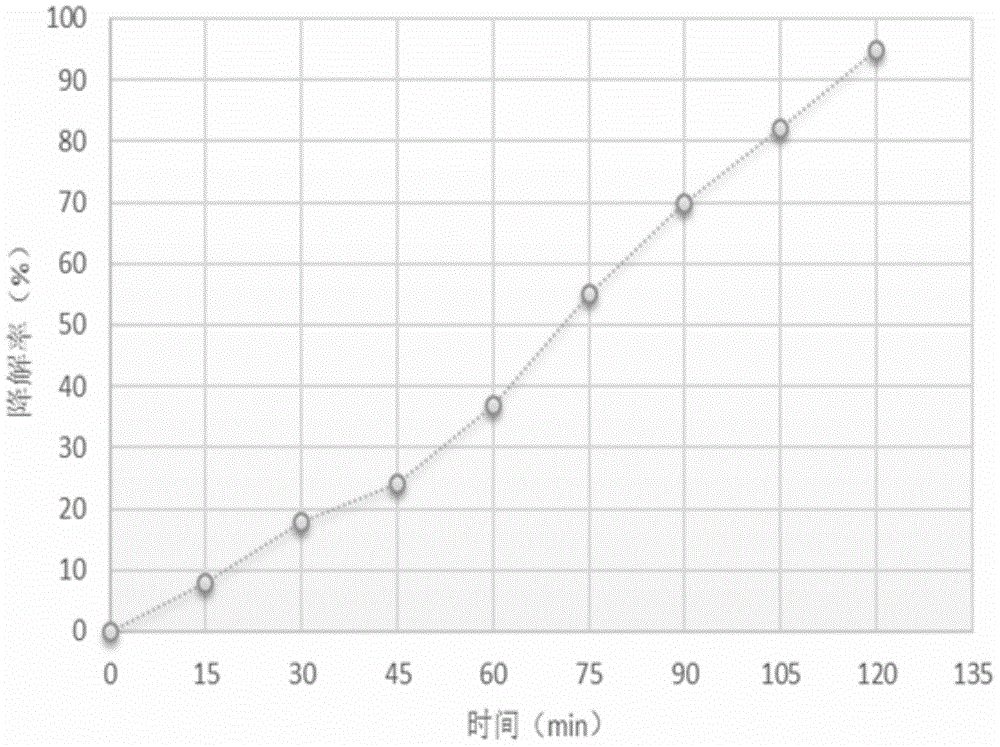
The invention relates to a surface photocatalytic modification method for an inorganic membrane, particularly a surface photocatalytic modification method for a water treatment inorganic membrane, which aims to solve the problem that the existing inorganic membrane can be easily influenced by the membrane pollution, can be easily blocked at the membrane pores and does not have the photocatalytic property. The method comprises the following steps: 1. putting the inorganic membrane in a reaction chamber, and preheating the inorganic membrane and reaction chamber body; and sequentially carrying out Ti source deposition, O source deposition, Ti source deposition, N source doping deposition, Zn source deposition, O source deposition, Zn source deposition and N source doping on the surface of the pretreated inorganic membrane to perform multiple-atomic-layer deposition, thereby obtaining the photocatalytic modified inorganic membrane for water treatment. The atomic layer deposition process is utilized to form the nitrogen-doped multicomponent composite photocatalytic deposition membrane. The inorganic membrane has favorable membrane pollution resistance, and the removal rate of methylene blue organic dyes by photocatalytic degradation is up to 95%.

Description

technical field [0001] The invention relates to a method for surface photocatalytic modification of an inorganic film for water treatment, in particular to a method for nitrogen doping on the surface of an inorganic film and multi-component composite photocatalytic modification based on an atomic layer deposition method. Background technique [0002] Under the conditions of water environment crisis and water shortage in the world today, membrane water treatment technology has become the leading technology in the field of new water treatment due to its outstanding advantages such as high efficiency, energy saving, good selectivity, and wide application range. Among them, inorganic membranes have become widely used membrane materials in membrane water treatment technology due to their significant advantages such as high temperature resistance, corrosion resistance, and high mechanical strength. However, the shortened service life of the membrane and the high cost of cleaning a...

Claims


Application Information

Patent Timeline
IPC IPC(8): C02F1/30B01J27/24
Inventor 田禹詹巍李宁张军孔令超
Owner HARBIN INST OF TECH
Learn More