Electrolytic furnace

An electrolysis furnace and furnace technology, which is applied to cells and other directions, can solve the problems of difficult electrolysis cell temperature, pollute the environment, waste energy, etc., and achieve the effect of preventing leakage, protecting the environment, and improving working conditions.

Active Publication Date: 2015-11-25
QIANDONG RARE EARTH GRP
View PDF9 Cites 8 Cited by
  • Summary
  • Abstract
  • Description
  • Claims
  • Application Information

AI Technical Summary

Problems solved by technology

This technical solution has defects such as transferring part of the energy to an environment that is not strongly related to the product, which wastes energy and pollutes the environment, and it is difficult to control the temperature of the electrolytic cell in a timely and accurate manner.

Method used


Image

  • Electrolytic furnace
  • Electrolytic furnace
  • Electrolytic furnace

Examples


Embodiment 1

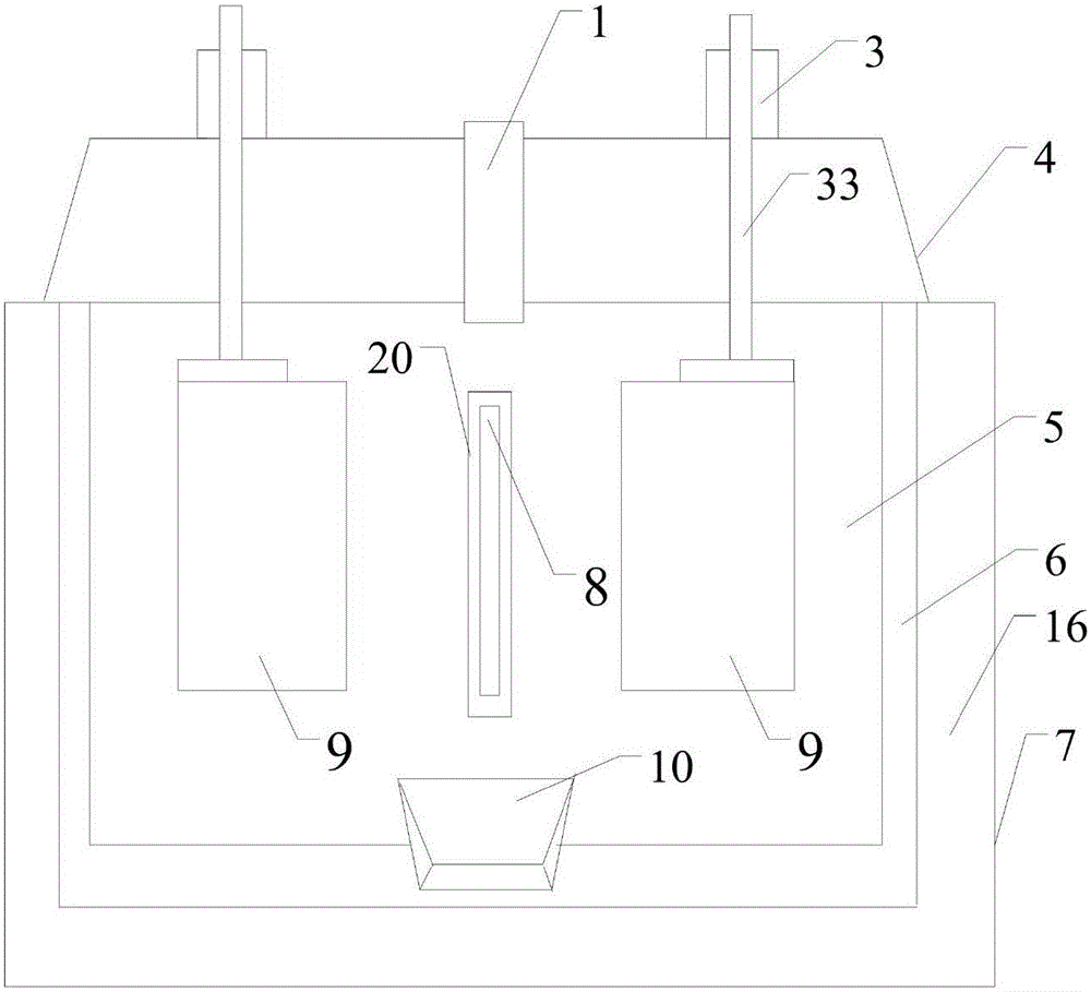
[0062] see figure 1 , Figure 7 .

[0063] Electrolytic furnace, including feed pipe 1, adjustment parts 3, sealing cover 4, furnace chamber 5, furnace wall 6, shell 7, cathode 8, graphite anode 9, crucible 10, fixing parts 11, jacketed water cooler 12, insulation layer 16 and anti-seepage insulating part 20. The shell 7 has an insulating layer 16 and a furnace wall 6 made of graphite material from the outside to the inside. The cavity in the furnace wall 6 forms a furnace 5 with an open top, and the top of the furnace 5 is provided with a sealing cover 4 to cover the insulation layer. 16 or more. One cathode 8 and two graphite anodes 9 are arranged in the furnace 5 . The cathode 8 is made of metal plate, one end is vertically suspended in the furnace 5, and the other end is a terminal 81, and the terminal 81 passes through the furnace wall 6 and the shell 7 to the outside of the shell 7; the terminal 81 A part of it is sealed and fixed in the furnace wall 6, the insulati...

Embodiment 2

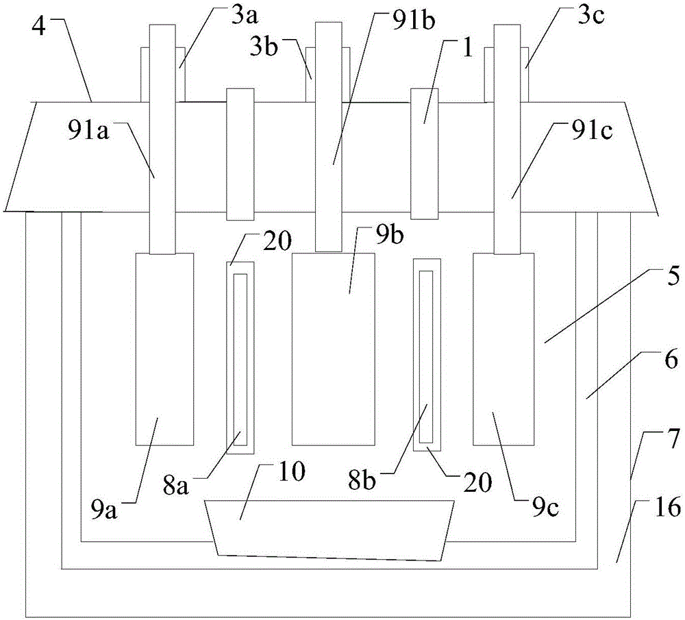
[0079] see figure 2 , Figure 7 .

[0080] An electrolytic furnace, including a feed pipe 1, an adjustment component 3, a sealing cover 4, a furnace chamber 5, a furnace wall 6, an outer casing 7, a cathode 8, an anode 9, a crucible 10, a water cooler 12, an insulating layer 16 and an anti-seepage insulating component 20 . There is an insulating layer 16 and a furnace wall 6 inside the shell 7, and the cavity in the furnace wall 6 forms a furnace 5 with an open top. A sealing cover 4 is arranged on the shell 7 to cover the shell 7 therein. The furnace 5 is provided with two cathodes 8a, 8b and three anodes 9a, 9b, 9c. Described each cathode 8 is a metal plate, one end outside the shell 7 to the inner wall of the furnace wall 6 is a terminal 81, and the other end passes through the shell 7 and the insulation layer 16 from the outside of the shell 7, and the furnace wall 6 is vertically suspended on the Inside the furnace 5 , it is sealed and fixed in the furnace wall 6 , ...

Embodiment 3

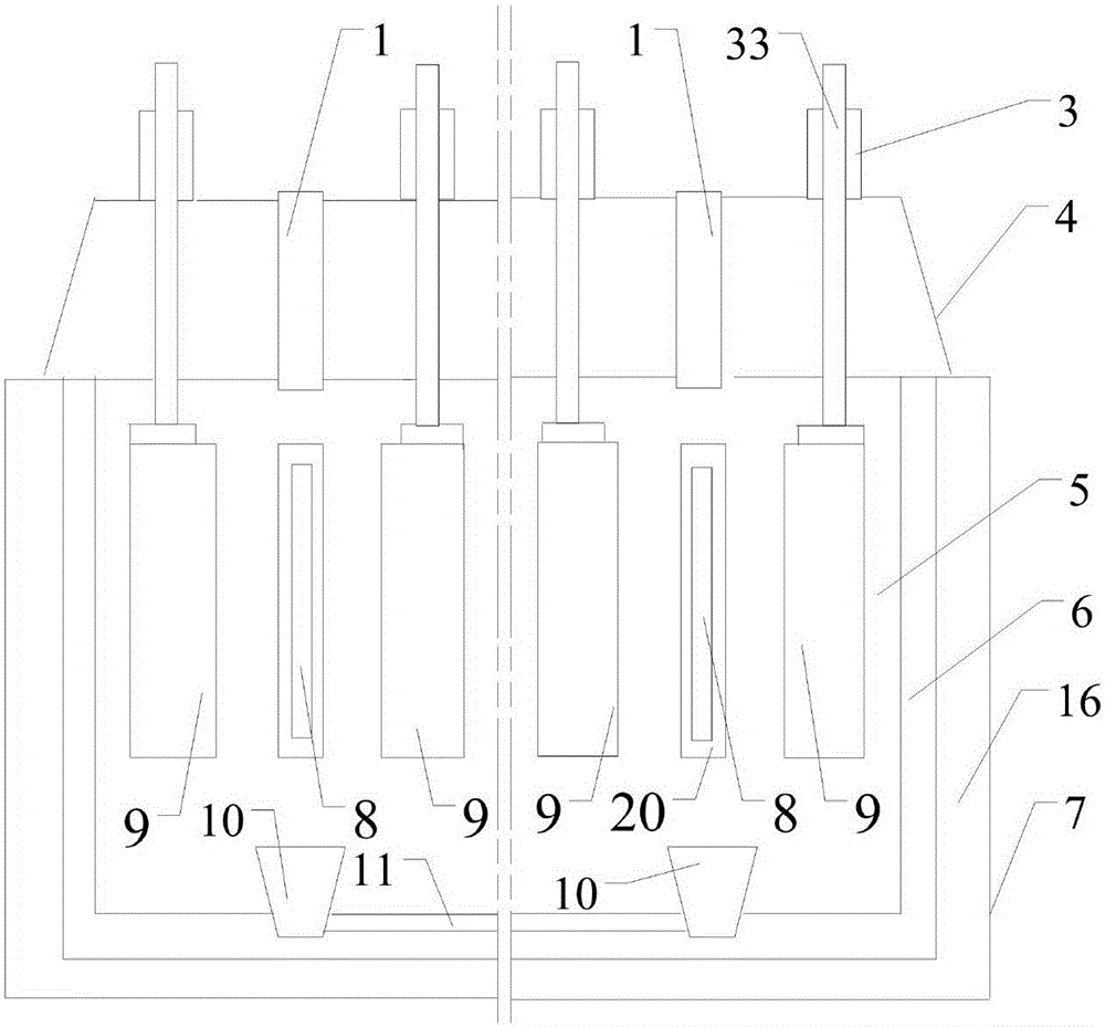
[0086] see image 3 , Figure 7 .

[0087] An electrolytic furnace, comprising a feed pipe 1, an adjustment component 3, a sealing cover 4, a furnace chamber 5, a furnace wall 6, a casing 7, a cathode 8, an anode 9, a crucible 10, a channel 11, a jacketed water cooler 12, an insulation layer 16 and Waterproof insulation part 20. There are insulation layer 16 and furnace wall 6 successively in described shell 7, and the cavity in furnace wall 6 forms the hearth 5 of top opening, and the top of hearth 5 is provided with sealing cover 4 and covers on insulation layer 16. Two cathodes 8 and four anodes 9 are arranged in the furnace 5 . One end of each cathode 8 passes through the shell 7 and the insulation layer 16, the furnace wall 6 is vertically suspended in the furnace 5 from the outside of the shell 7, and the other end outside the shell 7 becomes a terminal 81, which is connected to the power supply outside the furnace body. Each cathode 8 is sealed and fixed in the shel...


PUM


Abstract

The invention relates to an electrolytic furnace and belongs to the technical field of rare-earth metallurgical equipment and application of the rare-earth metallurgical equipment. The electrolytic furnace comprises an adjusting component (3), a sealing cover (4), a negative electrode (8), a positive electrode (9) and an impermeable insulating component (20). The negative electrode (8) and the positive electrode (9) are vertically distributed in parallel, and the positive electrode (9) can move to adjust the distance between the negative electrode and the position electrode. The electrolytic furnace has the beneficial effects that reaction gas is prone to escaping and easy to collect, products are easy to collect, slag generated in reaction is easy to clean, a product taking out component is easy to install, and the products are easy to take out; the service life of the negative electrode is long; a plurality of negative electrode and positive electrode sets can be arranged in the same electrolytic furnace to bring convenience to achieving large-scale and automatic production; energy is further saved, and clean production is achieved; and the negative electrode can be cooled by a cooling device to enhance the effect of preventing electrolyte from leaking, slow down oxidation loss of the negative electrode and reduce the resistance of the negative electrode.

Description

technical field [0001] The invention relates to an electrolytic furnace for producing rare earth metals and their alloys, an electrolytic furnace group composed of the electrolytic furnace and a use method. The invention belongs to the technical field of rare earth metallurgy equipment and application. Background technique [0002] In the production of rare earth metals and their alloys, electrolysis is a common production method. The electrolysis temperature for the production of rare earth metals and their alloys is usually above about 900°C. [0003] The publication date is February 13, 2013, and the publication number is CN102925931A, and the Chinese patent application titled "side insertion submerged lower cathode rare earth molten salt electrolytic cell" discloses "comprising: tank shell (10), side insertion cathode (1) , cathode conductive bar (2), insulating side wall (3), side fireplace lining (4), insulating ring (5), metal deflector (6), crucible (7), furnace bo...

Claims


Application Information

Patent Timeline
Patent Type & Authority Applications(China)
IPC IPC(8): C25C3/34C25C7/00
Inventor 龚斌蔡志双梁学民陈喜平王有山章立志刘明彪陈炎鑫谢楠林伟清
Owner QIANDONG RARE EARTH GRP
Why Eureka
Try Eureka