
Single-hole radar in-service bridge pile foundation quality detection method

A radar detection and bridge technology, applied in the direction of measuring device, infrastructure test, radio wave measurement system, etc., can solve the problems of complexity and lack of detection methods of bridge pile foundation detection in service, and achieve fast detection speed and simple operation , principle and reliable effect

Active Publication Date: 2015-11-25
RES INST OF HIGHWAY MINIST OF TRANSPORT +1
View PDF4 Cites 7 Cited by
  • Summary
  • Abstract
  • Description
  • Claims
  • Application Information

AI Technical Summary

Problems solved by technology

However, for the pile foundations of bridges in service, the pile tops are embedded in caps or pile caps. Due to the influence of various structures above the pile tops, the common detection methods introduced above cannot be directly applied. In view of the complexity of pile foundation detection problems in service bridges Due to the lack of effective detection means, the detection and evaluation of the technical status of the hidden engineering of the bridge pile foundation in service has become one of the important technical problems in the evaluation of the technical status of the bridge in service.

Method used


Image

  • Single-hole radar in-service bridge pile foundation quality detection method
  • Single-hole radar in-service bridge pile foundation quality detection method
  • Single-hole radar in-service bridge pile foundation quality detection method

Examples


Embodiment Construction

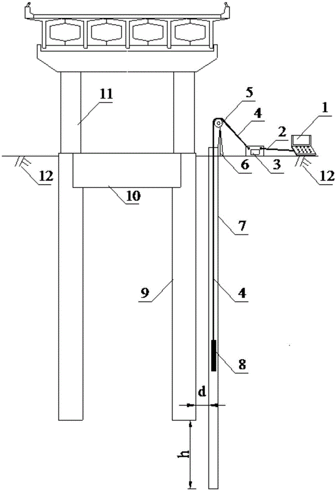
[0029] see figure 1 . figure 1 It is a schematic diagram of the method for detecting the quality of bridge pile foundations in service by single-hole radar in an embodiment of the present invention applied to the detection site, such as figure 1 As shown, the method for the quality of single hole radar detection service bridge pile foundation of the present invention may further comprise the steps:

[0030] S1: Drill a borehole parallel to the pile foundation 9 at a certain distance from the tested service bridge pile foundation 9 on the pile surrounding soil 12; wherein, the shortest distance between the drill hole and the tested service bridge pile foundation 9 is not more than 1 meter, and The depth of the borehole is greater than the depth of the detected service bridge pile foundation 9; the depth of the service bridge pile foundation 1 is determined according to the design drawings and construction records of the detected service bridge pile foundation 9; in one embodim...


PUM


Abstract

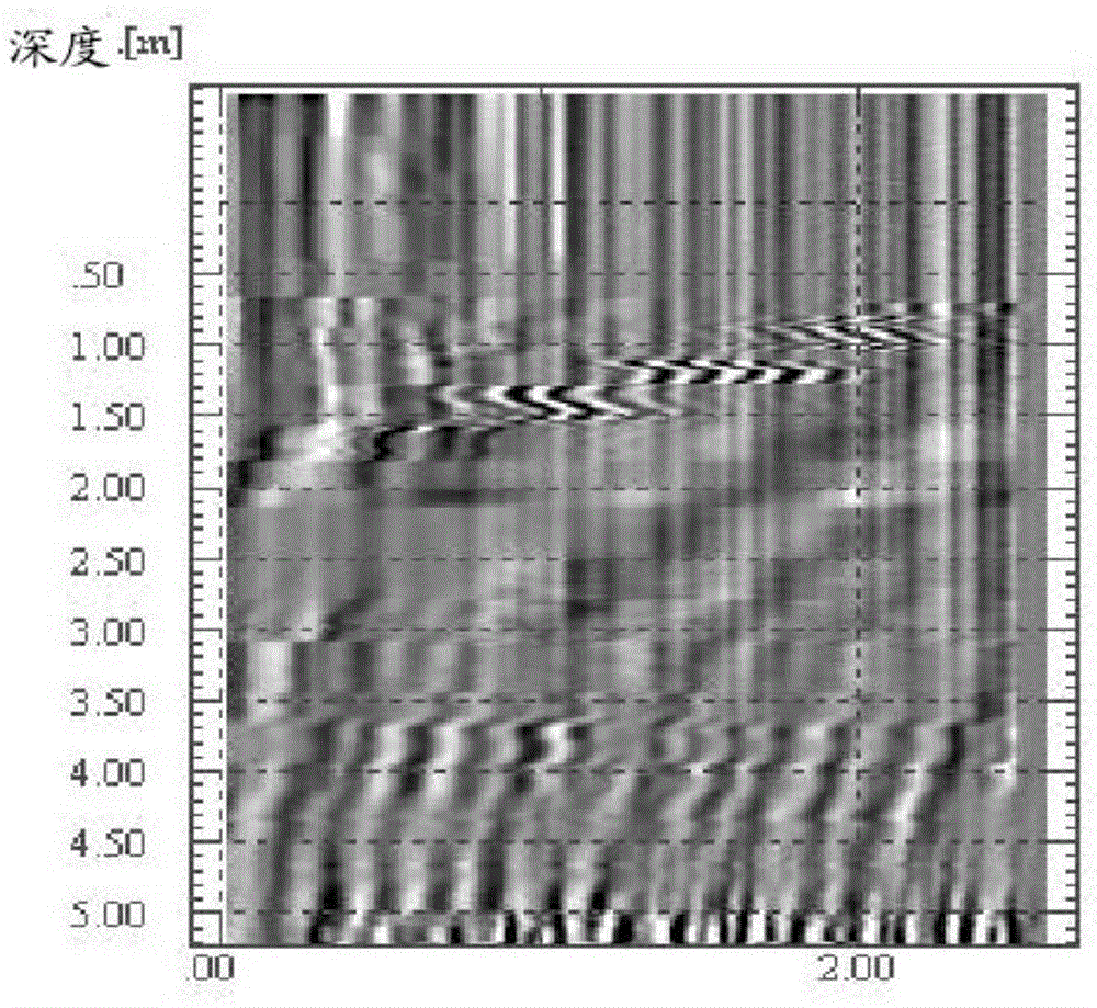
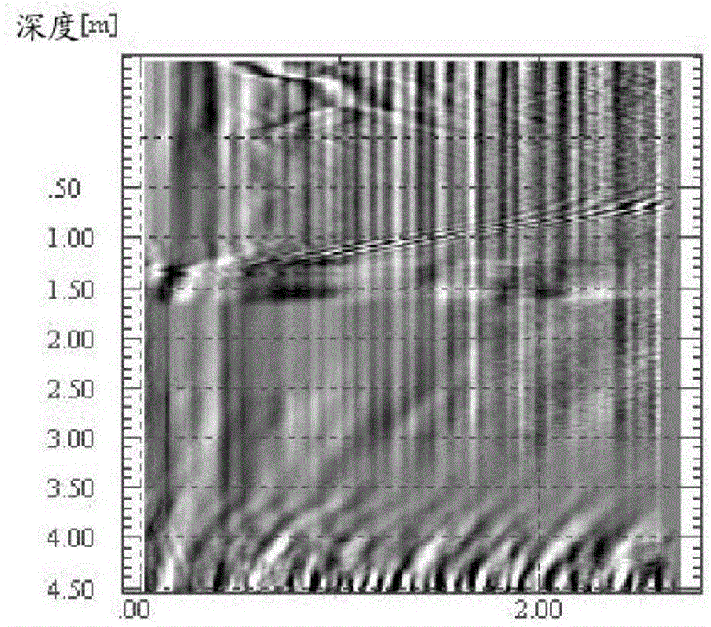
The invention discloses a single-hole radar in-service bridge pile foundation quality detection method. The single-hole radar in-service bridge pile foundation quality detection method comprises the following steps that a drill hole parallel to the detected in-service bridge pile foundation is drilled in the position a certain distance away from the detected in-service bridge pile foundation; a probe tube which can stretch into the drill hole is arranged and is tightly attached to the soil layer of the drill hole; a depth counter is arranged at an inlet of the drill hole, and the depth counter is provided with a pulley; a wire which is used for connecting a radar antenna to a radar main unit is wound across the pulley; the radar main unit is connected with a computer through a connecting line; the radar antenna is made to enter the probe tube, the radar main unit continuously emits electromagnetic wave signals around and receives electromagnetic wave reflection signals through the radar antenna; the radar antenna is made to move along the probe tube at a constant speed; the depth of the radar antenna is transmitted to the radar main unit through the depth counter; the electromagnetic wave reflection signals recorded by the radar main unit are processed through the computer, so that a longitudinal radar section image is formed; and the position of an abnormal image of the electromagnetic wave reflection signals of the in-service bridge pile foundation in the longitudinal radar section image is obtained, and the position is judged as the damage position of the in-service bridge pile foundation.

Description

technical field [0001] The invention relates to the field of pile foundation quality detection, in particular to a method for detecting the quality of pile foundations of bridges in service by single-hole radar. Background technique [0002] The bridge is the throat project in the highway traffic network, and as the foundation of an important part of the bridge, it plays a vital role in the safety of the bridge. Its safety is directly related to the normal and safe operation of the bridge structure. The pile foundation is the most widely used foundation form in my country's highway bridges. Among the more than 700,000 highway bridges in operation in China, most bridges use pile foundations. [0003] The pile foundation is a concealed project, deeply buried in the rock and soil, especially for the pile foundation of highway bridges, the pile diameter is large and the pile depth is deep, and the evaluation of its quality depends on effective detection technology. The pile fou...

Claims


Application Information

Patent Timeline
IPC IPC(8): E02D33/00G01S13/89
Inventor 马晔张理轻杨宇张学峰
Owner RES INST OF HIGHWAY MINIST OF TRANSPORT
Learn More