Cold-formed thin-walled ribbed U-shaped steel-encased concrete laminated slab composite beam

A cold-formed thin-walled, reinforced concrete technology, applied in buildings, building components, structural elements, etc., can solve the problem of difficult to ensure that steel beams and concrete work fully together, and can not improve the flexural rigidity and low shear bearing capacity of U-shaped steel beams. It can save materials and a lot of manpower, improve the longitudinal shear resistance, and reduce the amount of steel bars.

Inactive Publication Date: 2015-11-25
CHONGQING UNIV
View PDF9 Cites 13 Cited by
  • Summary
  • Abstract
  • Description
  • Claims
  • Application Information

AI Technical Summary

Problems solved by technology

The slice of the upper flange of the cold-formed thin-walled C-shaped steel beam is not easy to ensure the complete cooperation between the steel beam and the concrete due to its low shear bearing capacity
There is also a U-shaped steel-concrete composite beam in the prior art. When prefabricated concrete slabs are used, in order to ensure the bearing capacity of the U-shaped steel overhanging flange of the composite beam during construction, it is necessary to set a support at the lower part of the flange, and the concrete Cast-in-place slabs require a large number of templates; the angle steel required as a shear part requires a relatively large amount of welding, and the vertically stressed steel bars placed in the air cannot improve the bending stiffness of the U-shaped steel beam during the construction stage

Method used


Image

  • Cold-formed thin-walled ribbed U-shaped steel-encased concrete laminated slab composite beam
  • Cold-formed thin-walled ribbed U-shaped steel-encased concrete laminated slab composite beam

Examples


Embodiment Construction

[0025] The present invention will be further described below in conjunction with the accompanying drawings and embodiments, but it should not be understood that the scope of the subject matter of the present invention is limited to the following embodiments. Without departing from the above-mentioned technical ideas of the present invention, various replacements and changes made according to common technical knowledge and conventional means in this field shall be included in the protection scope of the present invention.

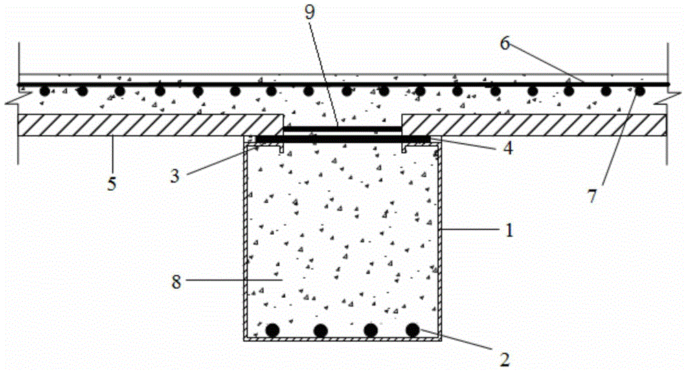
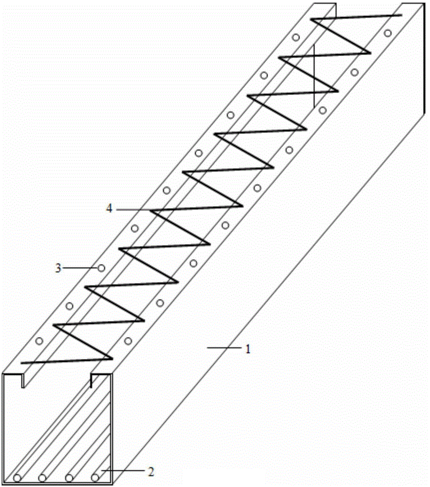
[0026] A cold-formed thin-walled ribbed U-shaped outsourcing steel-concrete composite slab composite beam, comprising a cold-formed thin-walled ribbed U-shaped steel beam 1, a full-length longitudinal stressed steel bar 2, a broken-line connecting steel bar 4, and prefabricated reinforced concrete Bottom plate 5, longitudinal reinforcement 6, transverse reinforcement 7, concrete 8 and inner longitudinal reinforcement 9 of reinforced concrete prefabricated sla...


PUM


Abstract

The invention discloses a cold-formed thin-walled ribbed U-shaped steel-encased concrete laminated slab composite beam, and belongs to a composite beam, for solving the problems that lots of formworks are needed, the construction period is long, and the production is difficult to realize industrialization in cast-in-place reinforced concrete beams and slabs. The cold-formed thin-walled ribbed U-shaped steel-encased concrete laminated slab composite beam comprises a cold-formed thin-walled ribbed U-shaped steel beam on a lower part, a precast concrete slab, a continuous longitudinal reinforcement cage, a broken-line type tie bar and concrete, wherein the cold-formed thin-walled ribbed U-shaped steel beam is provided with a bottom plate, two web plates and two internally-rolled flange plates, and exhaust holes are designed in each flange plate; and a concrete precast bottom plate is arranged on the upper flange of the ribbed U-shaped steel beam, and the concrete is poured on the surface layer of the concrete precast bottom plate, in strip-shaped through holes in end parts, and in the ribbed U-shaped steel beam. The cold-formed thin-walled ribbed U-shaped steel-encased concrete laminated slab composite beam disclosed by the invention is simple in structure, good in fire-resistant performance and overall stability, high in combination action, convenient and fast in construction, capable of realizing industrialized production, remarkable in economic benefits, and capable of being used in floor structures of civil engineering buildings.

Description

technical field [0001] The invention relates to a composite beam, in particular to a cold-formed thin-wall ribbed U-shaped composite beam covered with steel-concrete laminated plates, which belongs to the technical field of building structures. Background technique [0002] Outer-clad steel-concrete composite beams have been widely used in practical engineering because they can give full play to the tensile properties of steel and the compressive properties of concrete, and have the advantages of high rigidity and good stability. In order to ensure that there are enough steel bars to bear the tensile force on the lower part of the steel beam, the thickness of the bottom plate of the outsourcing steel is usually greater than the thickness of the web and flange, and the bottom plate and web are connected by welding. In order to ensure that the composite beam still has a certain bearing capacity in the case of fire, the composite beam generally needs to arrange additional firep...

Claims


Application Information

Patent Timeline
Patent Type & Authority Applications(China)
IPC IPC(8): E04C3/293E04B1/94
Inventor 刘界鹏朱兰影
Owner CHONGQING UNIV
Why Eureka
Try Eureka