Automatic temperature control dryer

A drying machine and drying room technology, applied in the directions of drying machine, drying, drying gas arrangement, etc., can solve problems such as difficulty in grasping when to turn on the fan, pueraria leaves are scattered, etc., and achieve stable and high drying temperature. quality effect

Inactive Publication Date: 2015-11-25
ANHUI KUDZUVINE ROOT PRODUCTIVITY PROMOTION CENT CO LTD
View PDF5 Cites 2 Cited by
  • Summary
  • Abstract
  • Description
  • Claims
  • Application Information

AI Technical Summary

Problems solved by technology

In a dryer using a boiler as a heating device, the temperature in the drying room is often controlled by turning on or off the fan of the boiler. It is difficult for technicians to know when to turn on the fan or when to turn off the fan. Blowing directly to the kudzu leaves, causing the kudzu leaves to be blown up and scattered

Method used


Image

  • Automatic temperature control dryer

Examples


Embodiment Construction

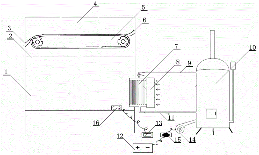
[0020] Examples such as figure 1 As shown, an automatic temperature control dryer includes a heating device, a drying device connected to the heating device and a control device. The heating device includes a boiler 10, a fan 14 and a heat exchanger 7. The fan 14 blows air into the boiler 10 to increase oxygen heating; the heating medium in the boiler 10 is oil. The heat exchanger 7 is connected to the boiler 10 by a high-temperature liquid delivery pipe 11 and a low-temperature liquid return pipe 9, the heat exchanger 7 includes a cooling pipe and a fan 8, and the drying device includes a heat exchange chamber 1, located in The drying chamber 4 above the heat exchange chamber 1 and the conveyor belt 5 located in the drying chamber 4, the two ends of the conveyor belt 5 are respectively provided with a feed port 6 and a discharge port 3, and the heat exchange chamber 1 is connected with the drying chamber. A partition 2 is arranged between the chambers 4, and a first air hole...


PUM


Abstract

The invention discloses an automatic temperature control dryer. The automatic temperature control dryer comprises a heat supplying device, a drying device connected with the heat supplying device and a control device. The heat supplying device comprises a boiler, a draught fan and a heat exchanger. The heat exchanger is connected with the boiler through a high temperature liquid conveying pipe and a low temperature liquid recirculatory pipe. The heat exchanger comprises a heat radiating tube and a fan. The drying device comprises a heat exchanging chamber, a drying chamber located on the heat exchanging chamber and a conveying belt located in the drying chamber. A feeding inlet and a discharging outlet are formed in the two ends of the conveying belt respectively. A partition plate is arranged between the heat exchanging chamber and the drying chamber. A first air hole is formed in the partition plate. The drying chamber is communicated with the outside through second air holes. The heat exchanging chamber is connected with the heat exchanger. According to the automatic temperature control dryer, the partition plate is provided with the air hole, so that the upflow of hot air is not influenced and waste happening due to the fact that leaves of kudzu roots fall into the heat exchanging chamber is avoided; the second air holes are formed above the two sides of the conveying belt, so that contamination to the leaves of the kudzu roots due to the fact that sundries such as dust and tree leaves from the outside fall into the leaves of the kudzu roots directly is avoided.

Description

technical field [0001] The invention relates to a drying device, in particular to an automatic temperature-control drying machine. Background technique [0002] During the kudzu root leaf drying process, it is necessary to strictly control the temperature in the drying room. If the temperature is too high, the water in the kudzu root leaves will evaporate excessively. If the temperature is too low, it will take a long time. The control of temperature requires real-time monitoring by professional technicians, which takes a lot of manpower. In a dryer using a boiler as a heating device, the temperature in the drying room is often controlled by turning on or off the fan of the boiler. It is difficult for technicians to know when to turn on the fan or when to turn off the fan. Blow directly to the Pueraria lobata leaves, causing the Pueraria lobata leaves to be blown up and scattered. Contents of the invention [0003] The object of the present invention is to provide an aut...

Claims


Application Information

Patent Timeline
Patent Type & Authority Applications(China)
IPC IPC(8): F26B21/10
Inventor 不公告发明人
Owner ANHUI KUDZUVINE ROOT PRODUCTIVITY PROMOTION CENT CO LTD
Why Eureka
Try Eureka