Clustered fiber Bragg grating sensor

A fiber grating and sensor technology, applied in the field of sensors, can solve the problems of low temperature detection resolution, cumbersome operation process, and large fusion loss, and achieve the effects of high detection resolution, simple operation process, and reduced fusion loss

Inactive Publication Date: 2015-11-25
8TH RES INST OF CETC
View PDF6 Cites 6 Cited by
  • Summary
  • Abstract
  • Description
  • Claims
  • Application Information

AI Technical Summary

Problems solved by technology

At present, a single fiber grating is often welded into a string, or a string of fiber gratings is used for temperature and strain detection. The operation process of these two methods is very cumbersome, and each grating needs to be packaged separately, and then the gratings are welded in series one by one. Complicated operation, high splice loss, difficult packaging, low survival rate
In addition, because the grating fusion needs to have a certain length, that is, the distance between the two gratings cannot be too short, so the resolution of temperature detection is low

Method used


Image

  • Clustered fiber Bragg grating sensor
  • Clustered fiber Bragg grating sensor
  • Clustered fiber Bragg grating sensor

Examples


Embodiment 1

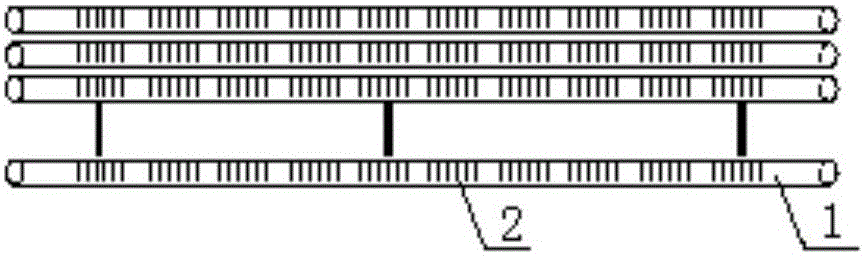
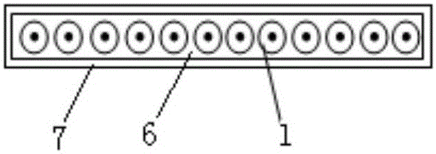
[0026] Such as figure 1 and figure 2 As shown, the bundled fiber grating sensor of the present invention includes twelve optical fibers 1, each of which is engraved with ten gratings 2, and the twelve optical fibers 1 engraved with ten gratings 2 adopt a planar bundled packaging method. The specific structure is as follows: twelve optical fibers 1 are distributed horizontally and in parallel, there are intervals between adjacent optical fibers 1 , and the distance between optical sensing centers of optical fibers 1 engraved with multiple gratings 2 is greater than 0.5 mm. In addition, the distance between the gratings 2 on the same optical fiber 1 is greater than or equal to 2mm, and twelve optical fibers 1 are located in a square protective sleeve 7 at the same time. The bundled optical fiber protection filler 6 is made of high temperature resistant fiber or thixotropic colloid. Square protective sleeves are generally made of metals such as ceramics and aluminum, and therm...

Embodiment 2

[0028] Such as image 3 As shown, the bundled fiber grating sensor of the present invention includes six optical fibers 1, each of which is engraved with a plurality of gratings 2, and the six optical fibers 1 engraved with a plurality of gratings 2 adopt a bundled tube packaging method, and its specific structure is : six optical fibers 1 engraved with a plurality of gratings 2 are respectively stuck in the trapezoidal groove 9 of a support frame 8, and the support frame 8 is wrapped with an inner protective sheath 10, a tape 11 and an outer protective sheath 12 from inside to outside. There are intervals between adjacent optical fibers 1, and the distance between the optical sensing centers of optical fibers 1 engraved with multiple gratings 2 is greater than 0.5mm. In addition, the distance between the gratings 2 on the same optical fiber 1 is greater than or equal to 2 mm. The strap 11 can be made of non-metal such as polyester plastic or metal such as aluminum strip and ...
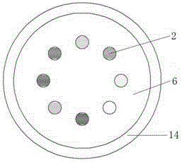
Embodiment 3

[0030] Such as Figure 4 As shown, the bundled fiber grating sensor of the present invention includes seven optical fibers 1, and each optical fiber 1 is engraved with a plurality of gratings 2, and a plurality of optical fibers 1 engraved with a plurality of gratings 2 adopts a bundled tube bundle packaging method, and its specific The structure is: seven optical fibers 1 engraved with multiple gratings 2 are concentrated in the middle of the inner protective sheath 10, there is an interval between adjacent optical fibers 1, and the optical sensing center distance of the optical fibers 1 engraved with multiple gratings 2 is greater than 0.5mm . In addition, the distance between the gratings 2 on the same optical fiber 1 is greater than or equal to 2 mm. Twelve reinforcing ropes 13 are distributed on the outer peripheral surface of the inner protective sheath 10 along the circumferential direction, and the outer protective sheath 12 is wrapped on the twelve reinforcing ropes ...


PUM


Abstract

The invention provides a clustered fiber Bragg grating sensor, which includes a plurality of optical fibers. Each optical fiber is provided with a plurality of gratings through the etching process. The plurality of optical fibers with the gratings etched thereon are clustered and packaged within a single plane or a beam tube. The clustered fiber Bragg grating sensor is small in splicing loss, simple in operation process, high in detection resolution, easy to package, high in survival rate and small in size. Meanwhile, the line detection, the surface detection and the body detection, subjected to large-area temperature strain, are enabled.

Description

Technical field: [0001] The invention relates to the technical field of sensors, specifically a sensor with small welding loss, simple operation process, high detection resolution, easy packaging, high survival rate, small volume, and capable of detecting line, surface, and volume of large-area temperature strain. Cluster fiber grating sensors. Background technique: [0002] Fiber Bragg Grating (FBG) is one of the most rapidly developed fiber optic passive devices in recent years. Since K.O.Hill of the Canadian Communications Research Center produced the world's first fiber Bragg grating (FBG) in 1978, due to its many unique advantages, people are increasingly committed to applying it to the sensing of various physical quantities. In 1989, W.W.Morey et al. reported for the first time that fiber gratings were used as sensors to measure temperature and strain, which opened a new chapter in the application research of fiber gratings in the field of sensing technology. Due to ...

Claims


Application Information

Patent Timeline
Patent Type & Authority Applications(China)
IPC IPC(8): G01D5/353G01D5/38
Inventor 孙兵刘亚南许丹丽李锦华王丹凤张文轩
Owner 8TH RES INST OF CETC
Why Eureka
Try Eureka