
Lateral laser pulse synchronous detection apparatus

A pulse synchronization and detection device technology, applied in the direction of testing optical performance, etc., can solve problems such as inability to test

Inactive Publication Date: 2015-11-25
PEOPLES LIBERATION ARMY ORDNANCE ENG COLLEGE
View PDF0 Cites 3 Cited by
  • Summary
  • Abstract
  • Description
  • Claims
  • Application Information

AI Technical Summary

Problems solved by technology

The disadvantage of this is to block the channel of the outgoing laser pulse to the target to be tested, which can only be tested in the test state, and cannot be tested in real time in the working state
At present, there is no instrument that can detect in real time whether the laser pulse emitted by the pulsed laser instrument is normal when it is working.

Method used


Image

  • Lateral laser pulse synchronous detection apparatus
  • Lateral laser pulse synchronous detection apparatus
  • Lateral laser pulse synchronous detection apparatus

Examples


Embodiment Construction

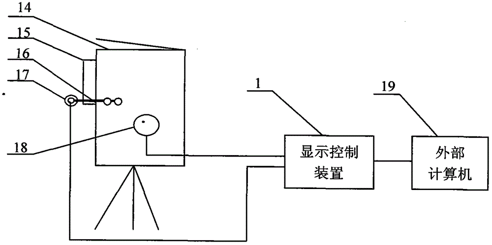
[0015] As shown in the figure, a side laser pulse synchronous detection device of the present invention includes an attached figure 2 The display control device 1, the conversion socket 18, and the photoelectric detector 17 are three parts;

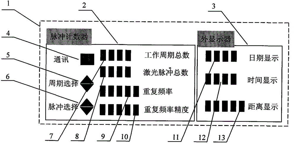
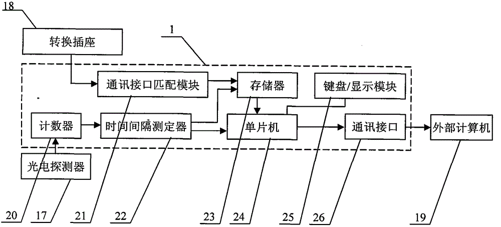
[0016] The display control device of the present invention includes an attached figure 1 Medium pulse counter 2, display control device 3, wherein the front panel of pulse counter 2 includes communication button 4, cycle selection button 5, pulse selection button 6, total number of irradiation cycles display area 7, total number of laser pulses display area 8, repetition frequency display area 9 1. Repetition frequency accuracy display area 10, the front panel of display control device 3 includes height display area 11, azimuth display area 12, and distance display area 13, wherein the internal circuit of display control device includes additional image 3 Middle counter 20, communication interface matching module 21, time interval meas...


PUM


Abstract

The invention discloses a lateral laser pulse synchronous detection apparatus, which comprises a display control device, a conversion device socket and a photoelectric detector. The display control device includes a pulse counter and an outer display. The photoelectric detector is assembled at the bottom of a laser emitting channel of a to-be-detected pulse laser apparatus through a fixing support. When the to-be-detected pulse laser apparatus is working, laser pulses scattering from atmosphere are received, photoelectric conversion from the laser pulses from electric pluses is achieved, the pulse counter receives pulse signals sent by the photoelectric detector, counting and testing of time intervals for the laser pulses are conducted, and functions of testing the work cycle frequency, laser range finding frequency, repetition rate and the like of the to-be-detected pulse laser apparatus are achieved. The lateral laser pulse synchronous detection apparatus will not affect operation of the to-be-detected pulse laser apparatus, is small in size, low in cost and high in automation, is convenient to operate and use, and plays a certain assistive effect in improving the performance and managing the technical state of the service life of the to-be-detected pulse laser apparatus.

Description

technical field [0001] The invention belongs to the technical field of laser testing, and relates to a device capable of synchronously detecting and displaying laser pulses emitted by pulsed laser instruments. Background technique [0002] With the development of laser technology, pulsed laser instruments are rapidly used in various fields of national economy and national construction such as long-distance ranging and three-dimensional scanning. The most typical application is the laser rangefinder. When it is working, the internal laser emits a beam of laser pulses with a compressed beam divergence angle. The pulse is reflected by the target in the hospital. The receiving amplifier circuit receives and shapes. The logic counting circuit inside the laser range finder accurately measures the time interval between sending and returning of the laser pulse emitted by the laser range finder, and calculates the distance from the measured target. [0003] In practical application...

Claims


Application Information

Patent Timeline
Patent Type & Authority Applications(China)
IPC IPC(8): G01M11/02
Inventor 沈洪斌李刚李三群刘秉琦胡文刚刘锋
Owner PEOPLES LIBERATION ARMY ORDNANCE ENG COLLEGE
Learn More