
Seawater sampling site suction filtration device

A suction filtration device, on-site technology, applied in sampling devices, preparation of test samples, etc., can solve the problems of sample loss, increased risk, complicated steps, etc., to achieve fast and efficient suction filtration, improve work efficiency, and easy to use. Effect

Inactive Publication Date: 2015-11-25
李洪涛
View PDF7 Cites 2 Cited by
  • Summary
  • Abstract
  • Description
  • Claims
  • Application Information

AI Technical Summary

Problems solved by technology

[0003] Most of the currently used seawater samplers are plexiglass samplers, which are small in size and need to be repeatedly put into the deep sea and then raised to the sea surface, which consumes physical strength and increases the risk due to the instability of the ship.
The current seawater sampling and filtration device has a slow suction and filtration speed due to poor airtightness. During seawater suction and filtration, the sample will be lost quickly, and multiple samplings are required, which increases the accidental error of the sample; because the container is small, it cannot To obtain a sufficient amount of sample by one-time suction filtration, multiple suction filtrations are required; after the sample is suction filtered, the suction filtration device needs to be disassembled and then the water sample is poured into a sample bottle of specified material
The operation requires at least two people to cooperate, the steps are cumbersome, the work efficiency is low, and it is easy to cause sample contamination

Method used


Image

  • Seawater sampling site suction filtration device
  • Seawater sampling site suction filtration device
  • Seawater sampling site suction filtration device

Examples


Embodiment Construction

[0012] Below in conjunction with accompanying drawing and embodiment the present invention will be further described:

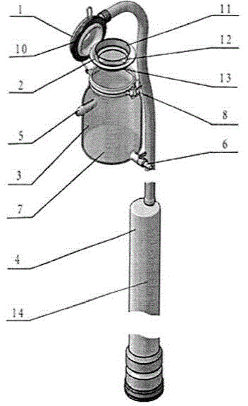
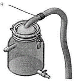
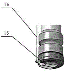
[0013] The specific embodiment of the present invention is shown in the figure, this kind of seawater sampling on-site filtering device is composed of a bottle stopper 1, a filter tray 2, a bottle body 3, and a sampling tube 4, and is characterized in that the bottle stopper 1 is provided with a sampling tube Joint 9, sealing ring 10; the lower edge of the filter tray 2 is provided with a sealing strip 13, the glass sand chip 12 is placed flat in the filter tray 2, and the filter membrane 11 is placed flat on the glass sand chip 12; the bottle stopper 1 is fixed by the buckle of the bottle stopper 8 is sealed and connected with the bottle body 3, and the filter tray 2 is pressed tightly, and the bottle stopper 1 and the bottle body 3 are sealed airtight through the sealing ring 10 and the sealing rubber strip 13; the bottle body 3 is provided with an air extra...


PUM


Abstract

The invention aims to provide a seawater sampling site suction filtration device which is composed of a bottle stopper, a filtration tray, a bottle body and a sampling pipe. The seawater sampling site suction filtration device is characterized in that a sampling pipe joint and a sealing ring are arranged on the bottle stopper; a sealing rubber strip is arranged on the lower edge of the filtration tray, a glass sand chip is flatly placed in the filtration tray, and a filter membrane is flatly placed on the glass sand chip; the bottle stopper is connected with the bottle body in a sealed mode through a bottle stopper fixing buckle and tightly presses the filtration tray, and the bottle stopper and the bottle body are sealed without leaking air through the sealing ring and the sealing rubber strip; the bottle body is provided with an air exhaust connector, a water outlet switch, a containing mark and the bottle stopper fixing buckle; the sampling pipe is provided with depth scales, the upper end of the sampling pipe is connected with the sampling pipe joint of the bottle stopper, and a one-way control valve and a one-way control valve pull line are arranged at the lower end of the sampling pipe. The seawater sampling site suction filtration device is simple in structure, convenient and flexible to use and widely applicable to sampling in water layers of different depths, and has the advantages that sampling is accurate, samples are free of pollution, suction filtration is fast and efficient, time and labor are saved and operation is safe.

Description

technical field [0001] The invention relates to the technical field of water body sampling, in particular to an on-site suction and filtration device for seawater sampling. Background technique [0002] Human activities have caused more and more serious pollution pressure on the marine environment. Regular measurement of the marine environment can grasp the pollution of seawater in a timely manner. At present, most of the sampling is carried out by the staff who arrive at the monitoring site by boat, put the seawater sampler into the deep sea to collect seawater, bring it out of the sea surface, and then use the suction filtration device to filter the samples, and finally transfer the filtered samples to a specific container. [0003] Most of the currently used seawater samplers are plexiglass samplers, which are small in size and need to be repeatedly put into the deep sea and then raised to the sea surface, which consumes physical strength and increases the risk due to the...

Claims


Application Information

Patent Timeline
Patent Type & Authority Applications(China)
IPC IPC(8): G01N1/14G01N1/34
Inventor 李洪涛刘阳于国庆王磊高文胜
Owner 李洪涛
Learn More