Fine particle measuring device and measuring method
A fine particle and measuring device technology, applied in the direction of measuring device, particle suspension analysis, suspension and porous material analysis, etc., can solve the problems of PM2.5 measurement error and unknown particle density, and achieve the effect of eliminating influence and measuring accurately
- Summary
- Abstract
- Description
- Claims
- Application Information
AI Technical Summary
Problems solved by technology
Method used
Image

Examples
Embodiment 1
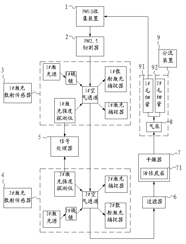
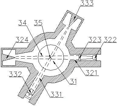
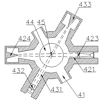
[0043] see figure 1 , figure 2 as well as image 3 , as shown in the legend therein, a fine particle measuring device is used to detect the content of PM2.5 in the air, comprising a PM10 collector 1 for collecting air samples, a device for separating fine particles in the air samples A PM2.5 cutter 2, a detection device for detecting the content of fine particles in air samples, a filter 6 for collecting fine particles in air samples, a dryer 7 for removing moisture in air samples, and An air pump 8 based on a stable air flow and a flow splitting device 9 for recycling the purified residual gas, the detection device includes,
[0044] A 1# laser scattering sensor 3, used to measure the scattering intensity of fine particles in air samples;
[0045] A 2# laser scattering sensor 4, used to measure the scattering intensity of fine particles in air samples;
[0046] a signal processor 5, configured to convert the scattering intensity of the fine particles into the concentration...
PUM
 Abstract
Description
Claims
Application Information