Equipment for accessing consumption amount of electricity, water, gas and heat to internet of things
A technology for accessing equipment and the Internet of Things, which is applied in the direction of measuring heat, calorimeters, and electrical components. It can solve the problems of low gas meter measurement accuracy, high operation and management costs, and narrow measurement range, achieving time-of-use prices, Solving the difficulty and low cost of meter reading
- Summary
- Abstract
- Description
- Claims
- Application Information
AI Technical Summary
Problems solved by technology
Method used
Image
Examples
Embodiment 1
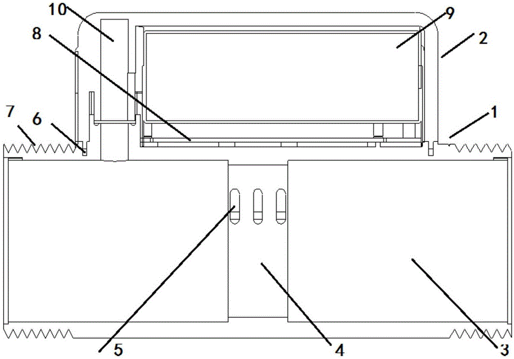
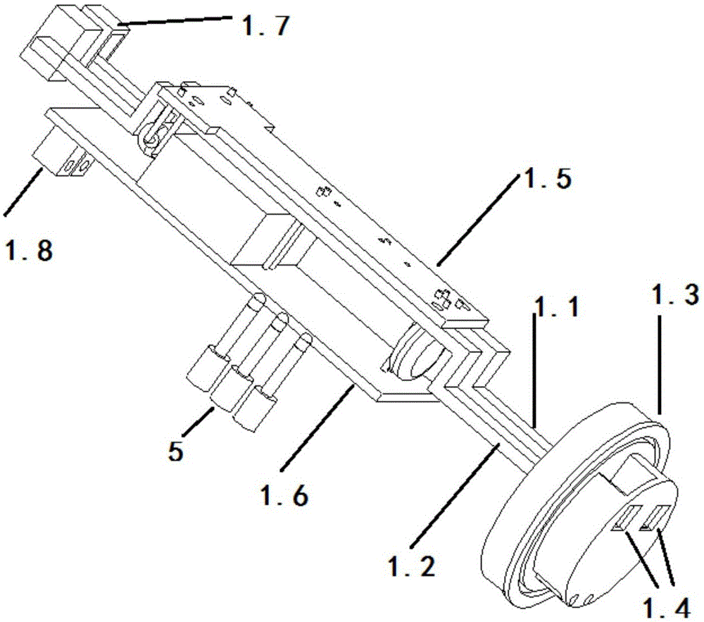
[0032] Embodiment one, such as figure 2 As shown, the electricity collection and sensing equipment includes an electricity metering circuit, a 220V incoming line interface 1.7, a calibration wiring port 1.4, and a calibration interface 1.8, and the electricity metering circuit includes a sampling shunt electrode 1.1, a through electrode 1.2, a control circuit 1.5 and The power supply circuit 1.6, the shunt electrode 1.1 and the two sides of the through electrode 1.2 are provided with fixed plastic parts 1.3, and the signal output terminal of the power metering circuit is connected to the connection electrode 5 through the optocoupler isolator 1.9.
[0033] combine as Figure 6 As shown, the mains is connected from the 220V incoming line interface, and the electricity metering circuit completes the electricity measurement, and through the optocoupler isolator 1.9, and figure 2 , figure 1 The connection electrode 5 in the connection is given to Figure 6 The main control ch...
Embodiment 2
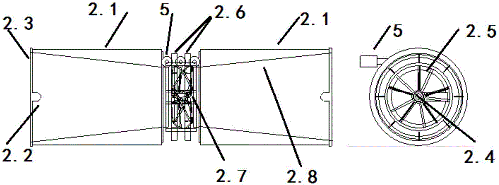
[0034] Embodiment two, such as image 3 combine Figure 6 As shown, the water volume acquisition sensing equipment includes a pipe body-2.1 installed symmetrically on both sides, a jet chamber-2.8 is provided on the left and right sides of the pipe body-2.1, and a rotor shaft is provided on the center line of the junction of the left and right jet chamber-2.8 Cover 2.7 and rotor shaft one 2.4, rotor shaft one 2.4 is provided with rotor one 2.5, and the dividing plate 2.6 that is arranged alternately on rotor one 2.5, water flow enters from any one pipe body one 2.1 on the left and right, can impact after being compressed by jet chamber one 2.8 Rotor 1 2.5 rotates, and the separators 2.6 arranged alternately by the rotors respectively cross between the electrodes on both sides of the middle electrode 5, and the separators 2.6 alternately arranged by the rotor 2.5 respectively cross between the two sides of the middle electrode, and the rotor 1 2.5 The rotation can change the c...
Embodiment 3
[0036] Embodiment three, such as Figure 4 combine Figure 6 As shown, the air volume acquisition and sensing equipment includes the pipe body 2 3.1 installed symmetrically on both sides, the left and right sides of the pipe body 2 3.1 are provided with jet chamber 2 3.0, and the center line of the junction of the left and right jet chamber 2 3.0 is provided with a rotor shaft Two 3.6, rotor shaft two 3.6 are provided with rotor two 3.5, the airflow enters from the left and right pipe body two 3.1, after being compressed by the jet cavity two 3.0, it can impact the rotation of rotor two 3.5, and the rotor two 3.5 is provided with a plurality of metal sheets installed at intervals 3.9, corresponding to the metal sheet 3.9, there is an inductance coil 3.7. When the metal sheet 3.9 alternately crosses the inductance coil, the change in the inductance value of the inductance coil makes the oscillation circuit connected to it oscillate or stop vibration, and generates pulse output ...
PUM
 Abstract
Description
Claims
Application Information
 - R&D Engineer
- R&D Manager
- IP Professional
- Industry Leading Data Capabilities
- Powerful AI technology
- Patent DNA Extraction
Browse by: Latest US Patents, China's latest patents, Technical Efficacy Thesaurus, Application Domain, Technology Topic, Popular Technical Reports.
© 2024 PatSnap. All rights reserved.Legal|Privacy policy|Modern Slavery Act Transparency Statement|Sitemap|About US| Contact US: help@patsnap.com


