Method for fast diagnosing direction connection of big power rectifier switch tube online

A rectifier switching tube, through-fault technology, used in instruments, measuring devices, measuring electricity and other directions

Active Publication Date: 2015-11-25
XUCHANG XJ SOFTWARE TECH +3
View PDF5 Cites 10 Cited by
  • Summary
  • Abstract
  • Description
  • Claims
  • Application Information

AI Technical Summary

Problems solved by technology

[0005] The purpose of the present invention is to provide a fast on-line diagnosis method for high-power rectifier switch tube strai

Method used


Image

  • Method for fast diagnosing direction connection of big power rectifier switch tube online
  • Method for fast diagnosing direction connection of big power rectifier switch tube online
  • Method for fast diagnosing direction connection of big power rectifier switch tube online

Examples


Embodiment 1

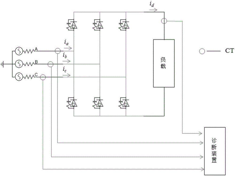
[0032] like figure 1 Shown is a schematic structural diagram of the rectifier, which is a full-bridge rectifier with three upper bridge arms and three lower bridge arms. The input terminal of the rectifier is a three-phase AC input, which are A phase, B phase and C phase respectively. In the three-phase input of the rectifier, each phase input has two bridge arms, which are divided into upper bridge arm and lower bridge arm. Each bridge arm One thyristor is connected in series on the arm, so the rectifier always has six thyristors. Three current detection points are respectively set on the three-phase input line of the rectifier, corresponding current acquisition devices are set at the current detection points, and current sensors for collecting DC current are also set on the DC output line of the rectifier. The three current detection points at the terminal and the current acquisition point at the output end are all connected to a diagnostic device, and the diagnostic device...

Embodiment 2

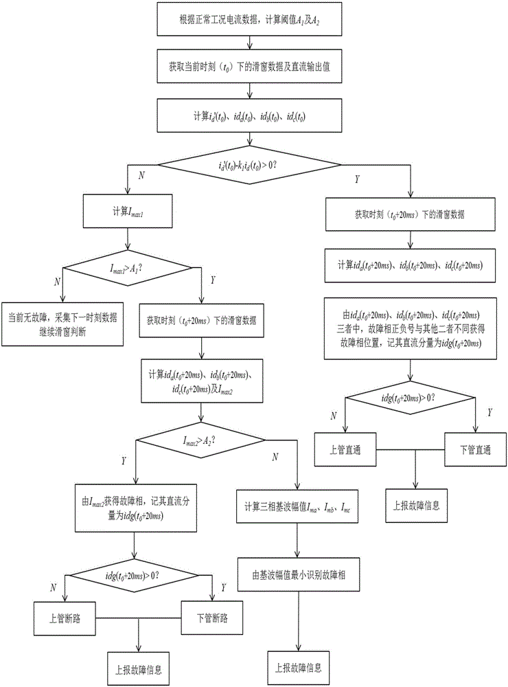
[0061] In Embodiment 1, the fault judgment method of the rectifier is: judging i d '(t 0 ) and k 1 × i d (t 0 ) size, when i d '(t 0 )>k 1 × i d (t 0 ), it is determined that the rectifier has a thyristor shoot-through fault, when i d '(t 0 )≤k 1 × i d (t 0 ), and when I max1 Greater than or equal to the preset threshold A 1 , the rectifier has an open circuit fault. In this embodiment, only the thyristor straight-through fault is judged for the rectifier, that is, there are only the following steps: when i d '(t 0 )>k 1 × i d (t 0 ), it is determined that the rectifier has a thyristor shoot-through fault. The specific implementation of this step has been described in detail in Embodiment 1, and will not be repeated here.

Embodiment 3

[0063] In Embodiment 1, the fault judgment method of the rectifier is: judging i d '(t 0 ) and k 1 × i d (t 0 ) size, when i d '(t 0 )>k 1 × i d (t 0 ), it is determined that the rectifier has a thyristor shoot-through fault, when i d '(t 0 )≤k 1 × i d (t 0 ), and when I max1 Greater than or equal to the preset threshold A 1 , the rectifier has an open circuit fault. In this embodiment, only the thyristor open-circuit fault judgment is performed on the rectifier, that is, only the following steps are performed: when i d '(t 0 )≤k 1 × i d (t 0 ), and when I max1 Greater than or equal to the preset threshold A 1 , the rectifier has an open circuit fault. The specific implementation of this step has been described in detail in Embodiment 1, and will not be repeated here.


PUM


Abstract

The invention discloses a method for fast diagnosing direction connection of a big power rectifier switch tube online, comprising steps of collecting practical output direct current value id (t0) of the rectifier at the moment of t0 and an instantaneous value ia (t0),ib (t0) and ic (t0) of three-phase input current at the moment to, calculating a theory output direct current value id'(t0) of the rectifier at the t0 moment according to the ia (t0),ib (t0) and ic (t0), comparing the id'(t0) and the id (t0), wherein when the id'(t0) is greater than the k1*id(t0), the rectifier has the switch tube direction connection fault, and the k1 is a set measurement reliable coefficient. The method disclosed by the invention is simple, has no complicated process, can perform the fault diagnosis only through comparing two data. Correspondingly, the diagnosis period is short, and the period from starting diagnosis and ending the diagnosis is very short. That is, when the rectifier is faulted, the trip protection occupies short time, which can effectively protect the rectifier and prevent the fact that the device is damaged because of operating for long time under the fault condition.

Description

technical field [0001] The invention relates to a fast on-line diagnosis method for a high-power rectifier switch tube through fault, and belongs to the technical field of fault diagnosis and relay protection of power electronic devices. Background technique [0002] With the wide application of high-power rectifiers in power transmission, chemical industry, metallurgy, railway and other industries, the failure of power electronic equipment has become increasingly prominent. The failure of rectifiers mainly refers to the failure of switching tubes in rectifier bridges. The reverse breakdown of the switch tube itself or the destruction of the insulating layer of the bridge arm will cause a short circuit of the switch tube, resulting in a rapid increase in current and a steep drop in conduction voltage drop. In severe cases, the device will be damaged and the system will be paralyzed; Poor wiring of the switch tube or overcurrent burnout will cause the switch tube to open circ...

Claims


Application Information

Patent Timeline
IPC IPC(8): G01R31/02
Inventor 刘星常仲学姜睿智杨远航宋国兵李国斌褚旭
Owner XUCHANG XJ SOFTWARE TECH
Why Eureka
Try Eureka