
Power divider with double-band filter function

A power divider, dual-band technology, applied in waveguide-type devices, connecting devices, electrical components, etc., to achieve the effects of low loss, high selectivity, and beneficial to integrated applications

Inactive Publication Date: 2015-11-25
SOUTH CHINA UNIV OF TECH
View PDF6 Cites 14 Cited by
  • Summary
  • Abstract
  • Description
  • Claims
  • Application Information

AI Technical Summary

Problems solved by technology

However, the article adopts the open-line resonator loaded symmetrically to form a filter network, and the miniaturization of the circuit still needs to be greatly improved.

Method used


Image

  • Power divider with double-band filter function
  • Power divider with double-band filter function
  • Power divider with double-band filter function

Examples


Embodiment

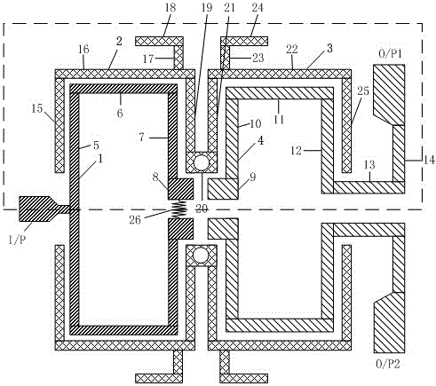
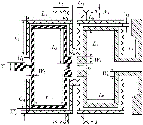
[0030] The structure of a power divider with dual-band filtering function is as follows figure 1 shown, the relevant dimensions are as figure 2 As shown, the thickness of the selected dielectric substrate is 0.81mm, the relative permittivity is 3.38, and the loss tangent angle is 0.0027. The specific circuit size is selected as follows: W 1 =1.86mm, W 2 =0.4mm, W 3 =0.4mm, W 4 =0.4mm, W 5 =1.3mm, W 6 =0.6mm, L 1 =7.4mm, L 2 =3.4mm, L 3 =6.4mm, L 4 =5.2mm, L 5 =7.6mm, L 6 =0.9mm, L 7 =6.8mm, L 8 =3mm, L 9 =4.8mm, G 1 =0.15mm, G 2 =0.5mm, G 3 =0.2mm, G 4 =0.2mm, G 5 =0.2mm, R =180Ω; the overall size is 17.5mm×22mm.

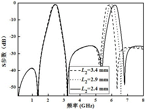
[0031] Such as image 3 Shown is the transmission characteristics of the dual-band band-pass filter circuit. It can be seen that by adjusting the length L of the loaded open line stub 2 , the operating frequency of the second passband can be independently controlled.

[0032] Such as Figure 4 Shown as S 11 parameter, S...


PUM


Abstract

The invention discloses a power divider with a double-band filter function, comprising an upper micro-strip structure, an isolation resistor, a medium dielectric substrate, and an underlying metal floor. The upper micro-strip structure includes four resonators, three feeders and one isolation resistor, and the upper micro-strip structure is arranged into two band-pass filter circuits of longitudinal symmetry. The power filter not only can achieve the characteristic of center frequency-adjustable double-bandpass filter, but also has the same characteristics as a power divider of which the power allocation ratio is 1:1. The resonators are quarter-wave short-circuit line resonators respectively loaded with a branch, and the characteristic of double-band bandpass filter with center frequency independently controllable is realized by adjusting the length of the branches. The resistor connecting two filter networks realizes matching of three ports of the circuit and isolation between two output ports. In addition, four transmission zeroes are introduced through source load coupling, which enables the power divider to have high selectivity and a good stop-band suppression effect, and is more conductive to integration and miniaturization of devices.

Description

technical field [0001] The invention relates to the technical field of miniaturized radio frequency circuits, in particular to a power divider with dual-band filtering functions that can be applied to radio frequency front-end circuits. Background technique [0002] With the rapid development of wireless communication, the demand for miniaturized radio frequency circuits is becoming more and more urgent. In wireless devices such as mobile communication and satellite communication, it is necessary to reduce the size of the device or accommodate more functional modules in a limited space, so miniaturization is an inevitable trend of development. Since the volume of the RF front-end occupies a large part of the wireless equipment, it is of great theoretical significance and application value to carry out in-depth research on its miniaturization. [0003] In the past, research on the miniaturization of radio frequency devices focused on the performance improvement and miniaturi...

Claims


Application Information

Patent Timeline
IPC IPC(8): H01P1/203H01P5/16
Inventor 章秀银张垚高立赵小兰
Owner SOUTH CHINA UNIV OF TECH
Learn More