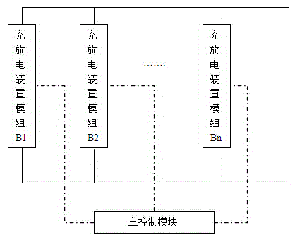
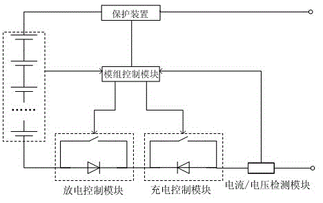
[0053] Describe technical scheme of the present invention in further detail below in conjunction with accompanying drawing: as figure 1 As shown, the control system that supports the addition of different types of charging and discharging devices with protection functions includes two or more parallel charging and discharging device modules and a main control module. The charging and discharging device modules communicate with each other through positive and negative interfaces The DC buses are connected in parallel for charging or discharging; figure 2 As shown, the charging and discharging device module includes a charging and discharging device, a charging control module, a discharging control module, a current/voltage detection module, a protection device and a module control module, and the charging and discharging device, a charging control module, a protection The device and the discharge control module are connected in series on the loop, and the current/voltage detection module is used to detect the current of the loop or the voltage of the bus bar; the sampling input terminal of the module control module is connected to the charging and discharging device, and the module controls The second sampling input terminal of the module is connected with the current/voltage detection module, the first control output terminal of the module control module is connected with the charge control module, and the second control output terminal of the module control module is connected with the discharge control module; The main control module is connected to the module control module; the protection device includes one or a combination of active protection devices and passive protection devices; the control input terminal of the active protection device is connected to the module control module, The detection end of the passive protection device is connected with the module control module.
[0054] The charging control module includes a first unidirectional conductive device and a first controllable switch element connected in parallel with the first unidirectional conductive device; the discharge control module includes a second unidirectional conductive device and a second unidirectional conductive device The second controllable switch element connected in parallel; the first controllable switch element and the second controllable switch element are respectively connected to the first control output end and the second control output end of the module control module; the first unidirectional The electric device and the second unidirectional conductive device are connected in series on the loop and conduct electricity in opposite directions.
[0055] like Figure 8 As shown, the charging control module is a charging MOS tube, and the discharging control module is a discharging MOS tube; since the MOS tube has a body diode inside, it also meets the requirements of the charging control module and the discharging control module. Figure 8 Protective devices are not shown.
[0056] The first unidirectional conductive device and the second unidirectional conductive device are diodes; the first controllable switch element and the second controllable switch element include but are not limited to relays or triodes.
[0057] The charging and discharging device includes at least one electric energy storage element connected in series, and the electric energy storage element includes but not limited to a physical battery or a chemical battery; the physical battery includes but not limited to a supercapacitor and a flywheel battery; The chemical batteries include but are not limited to lead-acid batteries, lithium-ion batteries, nickel-metal hydride batteries, and sodium-sulfur batteries.
[0058] The current detection module includes but not limited to a current detection resistor RSC or a Hall current sensor.
[0059] The active protection device is a switching device controlled by manual intervention; the active protection device includes but not limited to relays, triodes, IGBTs, and MOS tubes.
[0060] The passive protection device is a protection device that performs physical passive protection according to the current and voltage conditions; the passive protection device includes but is not limited to a fuse, a circuit breaker, and a temperature switch.
[0061] The control system with protection function and supporting the addition of different types of chargeable and discharging devices also includes a control host, and the control host is connected with the main control module.
[0062] The control host and the main control module are connected by including but not limited to I2C, CAN, RS-485, RS-232, USB, Bluetooth or wifi; the main control module and the module control module are connected by including but not limited to I2C , CAN, RS-485, RS-232, USB, Bluetooth or wifi connection.
[0063] The control system with protection function that supports the addition of different types of chargeable and discharging devices also includes a bus current sensor and a bus voltage sensor connected to the bus, and the bus current sensor and bus voltage sensor are connected to the main control module.
[0064] The control system that supports the addition of different types of charging and discharging devices with protection functions also includes a physical state monitoring module, which is used to detect the physical state of the charging and discharging device; the sampling terminal of the physical state monitoring module is connected to the charging and discharging device The device is connected, and the output terminal of the physical state monitoring module is connected with the module control module or the main control module.
[0065] The physical state monitoring module includes a temperature sensor, a chemical sensor, a coolant flow sensor, a smoke sensor, and a pressure sensor; wherein, the output terminals of the chemical sensor, the smoke sensor, the pressure sensor, and the coolant flow sensor are connected to the module control module, The output end of the temperature sensor is connected with the main control module.
[0066] like image 3 As shown, the control method that supports the addition of different types of rechargeable and discharge devices with protection functions includes an addition control step and a protection control step; the addition control step includes the following sub-steps:
[0067] S11: Before a new group of charging and discharging device modules are connected to the parallel circuit, the module control module sets the charging control module and the discharging control module to the off state;
[0068] S12: The module control module judges that the parallel circuit is in a charging state or a discharging state, and collects the voltage value of the charging and discharging device and the bus voltage value of the charging and discharging device:
[0069] (1) If the parallel circuit is in the charging state, judge whether the voltage value of the charging and discharging device and the bus voltage value and the difference meet the conditions for connecting to the parallel circuit:
[0070] (1-1) If the conditions for connecting to the parallel circuit are met, then connect the circuit and set the charging control module to the open state, that is, set the new set of charging and discharging device modules to the charging state;
[0071] (1-2) If the conditions for connecting to the parallel circuit are not met, the circuit will be connected again until the module control module detects that the parallel circuit is in a discharging state and the bus voltage is close to the voltage value of the charging and discharging device, and the The discharge control module is in the open state, that is, the new group of charging and discharging device modules is set to the discharge state;
[0072] (2) If the parallel circuit is in the discharge state, judge whether the voltage value of the charging and discharging device and the bus voltage value and the difference meet the conditions for connecting to the parallel circuit:
[0073] (2-1) If the conditions for connecting to a parallel circuit are met, then connect the circuit and set the discharge control module to the on state, that is, set the new set of charging and discharging device modules to the discharge state;
[0074] (2-2) If the conditions for connecting to the parallel circuit are not met, then the circuit will be connected again until the module control module detects that the parallel circuit is in the charging state and the bus voltage is close to the voltage value of the charging and discharging device, and set The charging control module is in the open state, that is, the new group of charging and discharging device modules is set to the charging state;
[0075] The protection control step includes the following sub-steps: in the process of adding the control step, the parallel circuit is protected by an active protection device and a passive protection device:
[0076] (1) When the current or voltage is too high, the passive protection device is automatically disconnected, and the module control module receives the message that the passive protection device is disconnected and uploads it to the main control module;
[0077] (2) When the physical state detection module detects an abnormality and uploads the message to the main control module, the main control module actively controls the charging and discharging device module that needs to be disconnected for protection; specifically, it is realized by controlling the on-off of the active protection device.
[0078] Described state of charge comprises the following substeps:
[0079] S2101: Before the charging process, all the charging control modules are in the open state, all the discharge control modules are in the closed state, and all the charging and discharging device modules are connected in parallel through the components of the charging direction allowed inside the discharge control module;
[0080] S2102: Start charging, and the charging current first enters the charging and discharging device module with the lowest voltage; the module control module samples the current/voltage passing through the current/voltage detection module, and also samples the voltage of the charging and discharging device:
[0081](1) When the module control module detects that there is a discharge current passing through the current detection module or the voltage value of the voltage detection module is the same as the bus voltage value, it indicates that the charging starts. When the module control module detects that the voltage of the charging and discharging device reaches the overcharge Threshold, indicating the end of charging; between the start of charging and the end of charging, set the discharge control module to the open state; until all the discharge control modules are in the open state, realize the parallel charging of all the charging and discharging device modules;
[0082] (2) When the module control module detects that the voltage of the charging and discharging device reaches the overcharging threshold, the module control module will put the charging control module in the off state; until all the charging control modules are in the off state, it means that all the charging and discharging device modules The charging of the group is completed.
[0083] In step S2102, the discharge control module is turned on at the beginning of charging to reduce the loss of the discharge control module.
[0084] like Figure 4 As shown, after the charging is completed, the discharge control module is in the open state, and the charge control module is in the closed state, which is the same as the initial state of the charge control module and discharge control module required for the battery discharge step. The equivalent circuit diagram is as follows Figure 5 shown.
[0085] Described discharge state comprises the following substeps:
[0086] S2201: Before the discharge process, all the charging control modules are in the closed state, all the discharging control modules are in the open state, and all the charging and discharging device modules are connected in parallel through the components of the discharge direction allowed inside the charging control module;
[0087] S2202: Start discharging, the charging and discharging device module with the highest voltage is the first to discharge; the module control module samples the current/voltage passing through the current/voltage detection module, and also samples the voltage of the charging and discharging device:
[0088] (1) When the module control module detects that there is a discharge current passing through the current detection module or the voltage value of the voltage detection module is the same as the bus voltage value, it indicates that the discharge starts. When the module control module detects that the voltage of the charging and discharging device reaches the over-discharge Threshold, indicating the end of discharge; between the start of discharge and the end of discharge, set the charging control module to the open state; until all the charging control modules are in the open state, realize the parallel discharge of all charging and discharging device modules;
[0089] (2) When the module control module detects that the voltage of the charging and discharging device reaches the over-discharge threshold, the module controlling module puts the discharging control module in the closed state; until all the discharging control modules are in the closed state, it means that all the charging and discharging device modules All groups are discharged.
[0090] In step S2202, the charging control module is turned on at the beginning of discharging to reduce the loss of the charging control module.
[0091] like Image 6 As shown, after the discharge is completed, the charging control module is in the open state, and the discharge control module is in the closed state, which is the same as the initial state of the charging control module and the discharging control module required by the charging state. The equivalent circuit diagram is as follows Figure 7 shown.
[0092] The control method that supports the addition of different types of charging and discharging devices with protection functions also includes a step of judging whether there is a parallel charging and discharging device module in the parallel circuit: after step S1, it is judged whether there is a charging and discharging device in the existing parallel circuit Module: if it exists, go to step S2; if there is no direct connection to the bus, charge or discharge according to the requirement.
[0093] The control method that supports the addition of different types of charging and discharging devices with protection functions also includes a judgment whether a new group of charging and discharging device modules to be connected is in a fault state: after step S1, it is judged that the new group of charging and discharging devices Whether the module is in fault state: if yes, end, if not, go to step S2.
[0094] The control method that supports the addition of different types of charging and discharging devices with protection functions also includes a real-time detection step: when it is detected that the bus voltage difference is too large, a small number of charging and discharging device modules with higher voltages are cut off, and then the voltage is connected externally. Lower charging and discharging device module.