Motor end cover assembly machine

A technology for motor end caps and assembly machines, which is applied in the direction of electromechanical devices, manufacturing motor generators, electrical components, etc., can solve the problems of manual assembly of motor end caps, such as laborious automation, to achieve automatic assembly, good automation, and reduce labor costs cost effect

Active Publication Date: 2015-11-25
TONGXIANG SHENGHUI PRECISION MACHINERY
View PDF5 Cites 25 Cited by
  • Summary
  • Abstract
  • Description
  • Claims
  • Application Information

AI Technical Summary

Problems solved by technology

[0003] The invention provides a motor end cover assembly machine capable of separating materials and assembling the motor end cover onto the motor casing, which solves the problems of manual assembly of the motor end cover, which is laborious and has a low degree of automation

Method used


Image

  • Motor end cover assembly machine
  • Motor end cover assembly machine
  • Motor end cover assembly machine

Examples


Embodiment 1

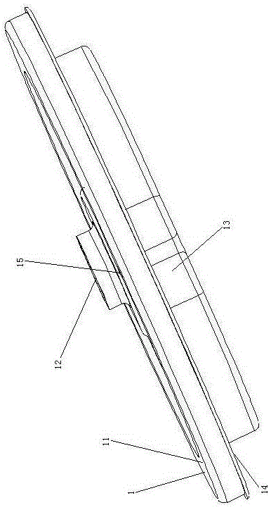
[0033] Embodiment one, see figure 2 , a motor end cover assembly machine, including a frame 2, a motor end cover storage mechanism 3, a material distribution mechanism 4 and a motor end cover pre-installation mechanism 6.

[0034] The right side of the frame 2 is provided with a motor housing fixing structure 21 . The motor housing fixing structure 21 is a manipulator, and of course it is possible to use a suction cup for adsorption and fixation, or a clamp for clamping and fixing. The right end of the frame 2 is provided with a first motor 5 and a bottom bracket 22 fixedly connected thereto. The first motor 5 is positioned at the lower end of the frame, which is conducive to keeping the center of gravity stable. The bottom bracket 22 is provided with a discharge hole passing through the bottom bracket along the up and down direction. A turntable 23 is rotatably connected to the bottom bracket 22 . Turntable 23 is horizontal setting. The turntable 23 is driven to rotate ...

Embodiment 2

[0049] Embodiment two, the difference with embodiment one is:

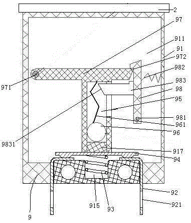
[0050] see Figure 9 , The rack 2 is provided with a tilting self-power-off switch 9 . The tilt self-cutting switch 9 includes a shell 91 and a connecting pin 92 . The shell 91 is fixedly connected with the frame 2 . The power supply of the electrical components on the present invention is introduced through inclination self-cutting switch 9.

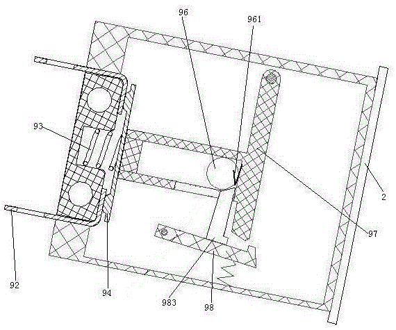
[0051] see Figure 10 , The tilt self-disconnecting switch 9 also includes a power-disconnecting spring 93 , a conductive sheet 94 , a weight guide cavity 95 , a weight 96 , a swing arm 97 and a barb 98 .

[0052] The shell 91 is made of insulating material, specifically made of plastic. The shell 91 is connected with the frame 2 together. The housing 91 is provided with an assembly cavity 911 . A recess 915 is formed in the middle of the bottom wall of the assembly cavity 911 .

[0053] There are two connecting pins 92. The two connecting pins 92 are distributed a...


PUM


Abstract

The invention relates to a device for motor production. A motor end cover assembly machine comprises a rack, wherein the rack is provided with a motor shell fixing structure, a motor end cover storage mechanism, a separation mechanism and a motor end cover pre-installation mechanism, the motor end cover storage mechanism is provided with a vertically-arranged motor end cover penetrating connection rod, the separation mechanism is used for separating motor end covers sleeved on the motor end cover penetrating connection rod one by one, and the motor end cover pre-installation mechanism is used for transferring and assembling the motor end covers separated by the separation mechanism onto a motor shell arranged in the motor shell fixing structure. The invention provides a motor end cover assembly machine by which the motor end covers can be installed on motor shell, and the problems of labor waste existing in manual assembly of the motor end covers and low automatic degree are solved.

Description

technical field [0001] The invention relates to equipment for motor production, in particular to a motor end cover assembly machine. Background technique [0002] The motor includes a housing, electronics disposed in the housing, and a rotor located in the stator. The rotor is connected to a rotating shaft (motor shaft), at least one end of the housing is connected to a motor end cover, and the rotating shaft passes through the motor end cover. Promptly disclose a kind of motor in the patent document of Chinese Patent Publication No. CN104539078, entitled "Permanent Magnet Brushless Motor with Dust Structure on Rotor". Motor end caps such as figure 1 As shown, the motor end cover 1 includes an end cover body 11, and a shaft hole 12 is arranged in the middle of the end cover body 11. The inner end surface of the end cover body 11 protrudes inwardly to form a mounting boss 13, and the mounting boss 13 and the end cover body 11 forms an annular step 14, and the end cover body...

Claims


Application Information

Patent Timeline
Patent Type & Authority Applications(China)
IPC IPC(8): H02K15/14
Inventor 方勇王新生陈林生徐卫宏刘小雄
Owner TONGXIANG SHENGHUI PRECISION MACHINERY
Why Eureka
Try Eureka