Supercharge Your Innovation With Domain-Expert AI Agents!

MEMS Microphone

A micro-electromechanical system and microphone technology, which is applied in the direction of electrostatic transducer, microphone, etc., can solve the problem that the diaphragm 108 cannot work normally.

Active Publication Date: 2019-05-03
SOLID STATE SYST
View PDF7 Cites 0 Cited by
  • Summary
  • Abstract
  • Description
  • Claims
  • Application Information

AI Technical Summary

Problems solved by technology

As a result of examining the MEMS microphone by the present invention, its sound hole 208 is directly connected to the cavity 112, therefore, as figure 1 Similar to the microparticles 128 of the same, it is also likely to enter the chamber 124, causing the diaphragm 108 to not work properly

Method used


Image

  • MEMS Microphone
  • MEMS Microphone
  • MEMS Microphone

Examples


Embodiment Construction

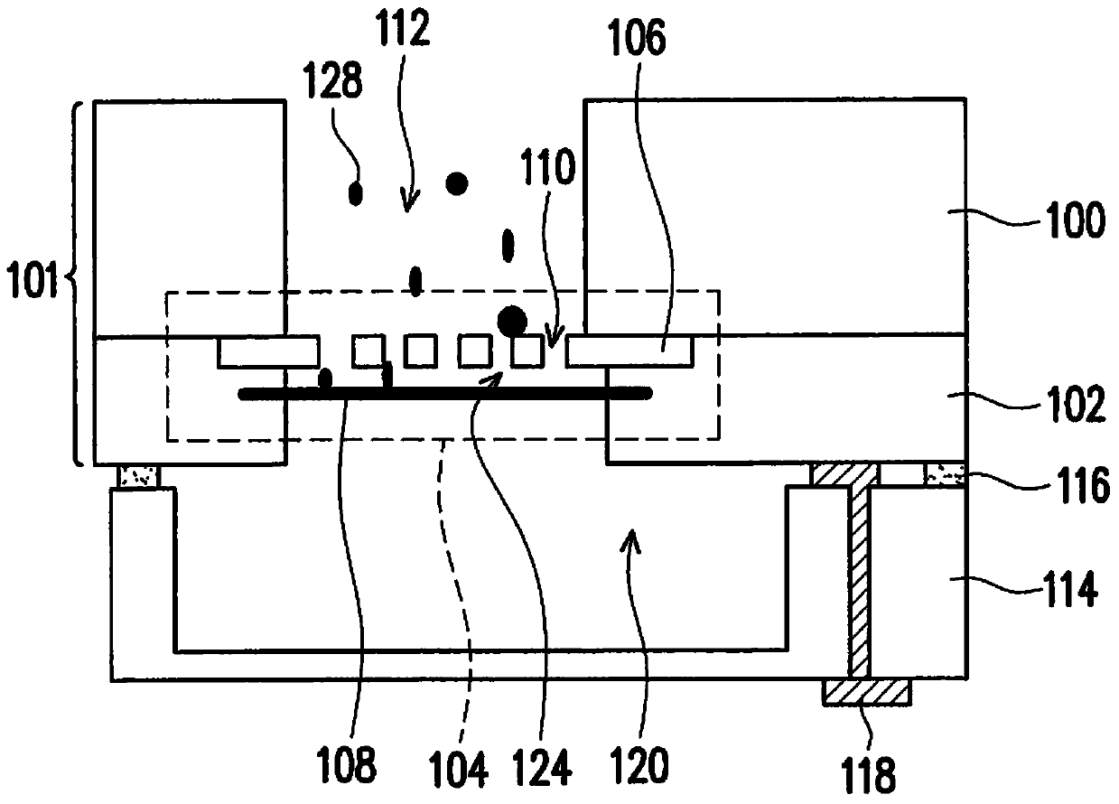
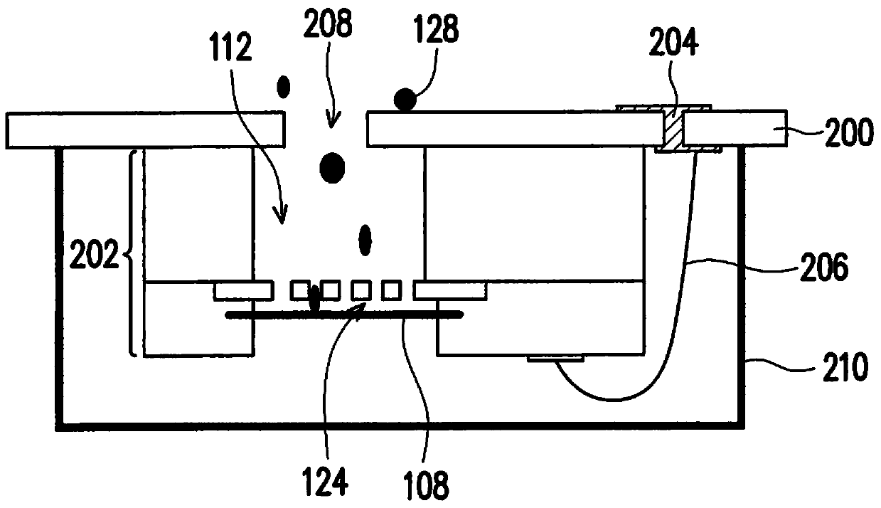
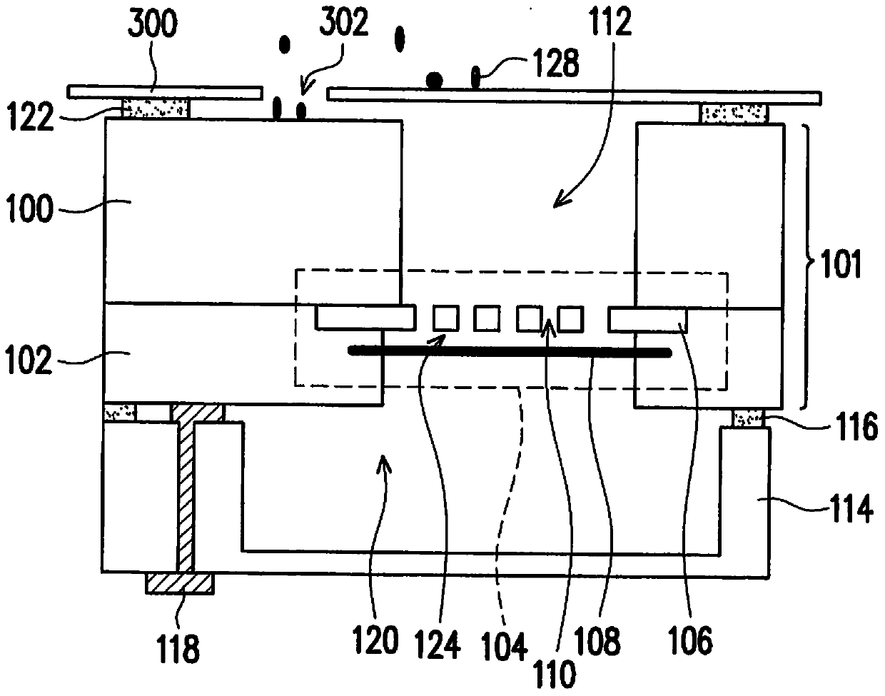
[0041] The present invention considers that the micro-particles of the traditional MEMS microphone may enter the cavity through the sound hole, and then enter the cavity through the through hole, which may cause the performance of the diaphragm to decrease, or even fail to work. The present invention proposes multiple embodiments to facilitate description, but is not limited to the cited embodiments, and appropriate combinations are also allowed among the multiple listed embodiments.

[0042] image 3 is a schematic cross-sectional view of a MEMS microphone according to an embodiment of the present invention. Figure 4 is according to image 3 Schematic diagram of the top perspective structure of a part of the microelectromechanical system microphone structure. refer to image 3 and Figure 4 , the MEMS microphone structure includes a MEMS structure 101 with a substrate 100 , a backplate 106 and a diaphragm 108 , wherein the substrate 100 has a cavity 112 , and the backpla...


PUM


Abstract

The invention discloses a micro-electro-mechanical system microphone, which includes a micro-electro-mechanical system structure and has a substrate, a diaphragm and a back plate. The substrate has a cavity, and the back plate is between the cavity and the diaphragm. The back plate A plurality of through holes are connected to the cavity so that the cavity extends to the diaphragm. In addition, an adhesive layer is disposed on the substrate and surrounds the cavity. The cover plate is adhered to the adhesive layer, and the cover plate has a sound hole. The position of the sound hole is staggered with the cavity and is not directly connected.

Description

technical field [0001] The present invention relates to a Micro-Electrical-Mechanical System (MEMS) microphone, and in particular to a Micro-Electrical-Mechanical System microphone with a dust-proof effect. Background technique [0002] Micro-electro-mechanical system microphone is a kind of tiny microphone, which is also a component completed by semiconductor manufacturing process, and can be connected with integrated circuits of semiconductor manufacturing process. [0003] figure 1 A conventional MEMS microphone is shown. refer to figure 1 , a conventional MEMS microphone includes a MEMS structure 101 . The MEMS structure 101 includes a substrate 100 . The substrate 100 is, for example, a semiconductor substrate, or, for example, a silicon substrate. Using photolithography and etching in the semiconductor manufacturing process, the substrate 100 forms a cavity (Cavity) 112 for receiving an external sound source. On the other side of the substrate 100 there is at lea...

Claims


Application Information

Patent Timeline
IPC IPC(8): H04R19/04
Inventor 谢聪敏李建兴蔡振维刘志成
Owner SOLID STATE SYST
Features
  • R&D
  • Intellectual Property
  • Life Sciences
  • Materials
  • Tech Scout
  • Unparalleled Data Quality
  • Higher Quality Content
  • 60% Fewer Hallucinations
Learn More