Bag turning centrifugal machine

A centrifuge and bag-turning technology, which is applied in the field of bag-turning centrifuges, can solve the problems that the seal between the feeding pipe and the push rod is easily damaged, cannot be used for the separation of toxic materials, and affects the service life of the centrifuge, etc., and achieves good sealing performance and low noise , the effect of small footprint

Active Publication Date: 2015-12-02
ZHANGJIAGANG ZHONGNAN CHEM MACHINERY
View PDF9 Cites 3 Cited by
  • Summary
  • Abstract
  • Description
  • Claims
  • Application Information

AI Technical Summary

Problems solved by technology

[0003] The feeding method of the existing bag-turning centrifuge is as described in the patent 200480006484.5 bag-turning filter centrifuge. The material is fed from the rear of the centrifuge to the drum by passing the feeding pipe through the hollow push rod in the main shaft. , this feeding method not only makes the structure of the centrifuge complicated, but also the seal between the feeding tube and the push rod is easily damaged, which affects the service life of the centrifuge, and it cannot be used for materials that will deteriorate in contact with the air or poisonous materials that will pollute the environment if leaked out. material separation
In addition, since the position of the feeding tube remains unchanged when the push rod is pushed out, it is easy for the material to contaminate the inner cavity of the push rod
[0004] There are also some inverted bag centrifuges that use a feed pipe on the front cover to feed the material. In order to push the filter bag out of the inverted bag centrifuge with this structure, the front cover needs to be opened, which is also not suitable for use with air. Separation of toxic materials that will deteriorate in contact with materials or leak out that will pollute the environment

Method used


Image

  • Bag turning centrifugal machine
  • Bag turning centrifugal machine
  • Bag turning centrifugal machine

Examples


Embodiment Construction

[0030] Specific embodiments of the present invention will be described in detail below in conjunction with the accompanying drawings.

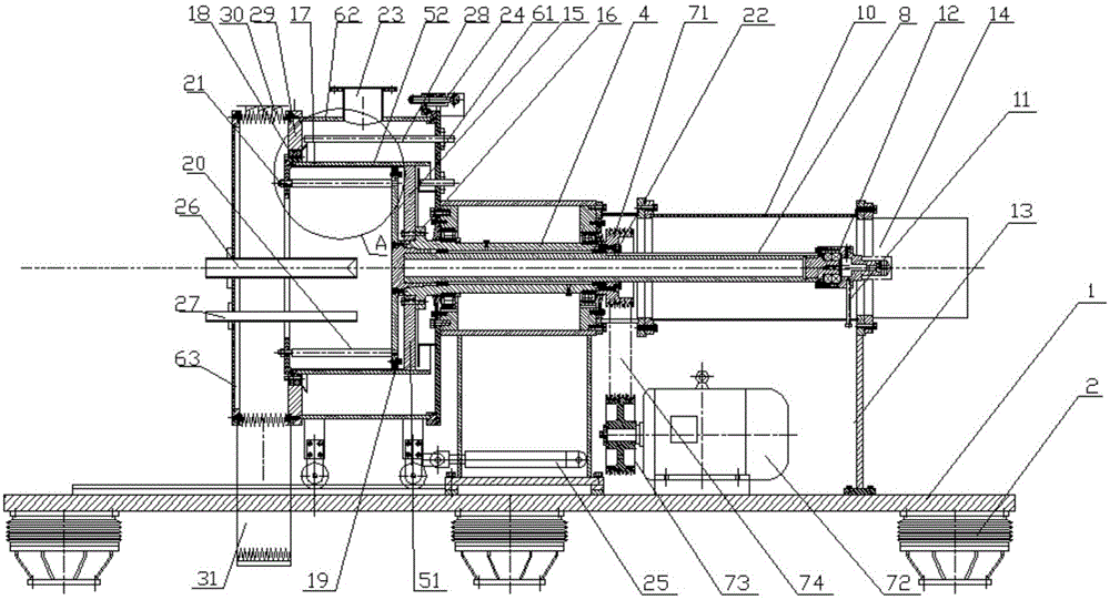
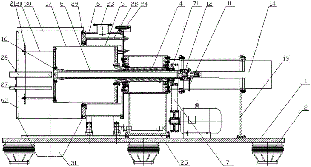
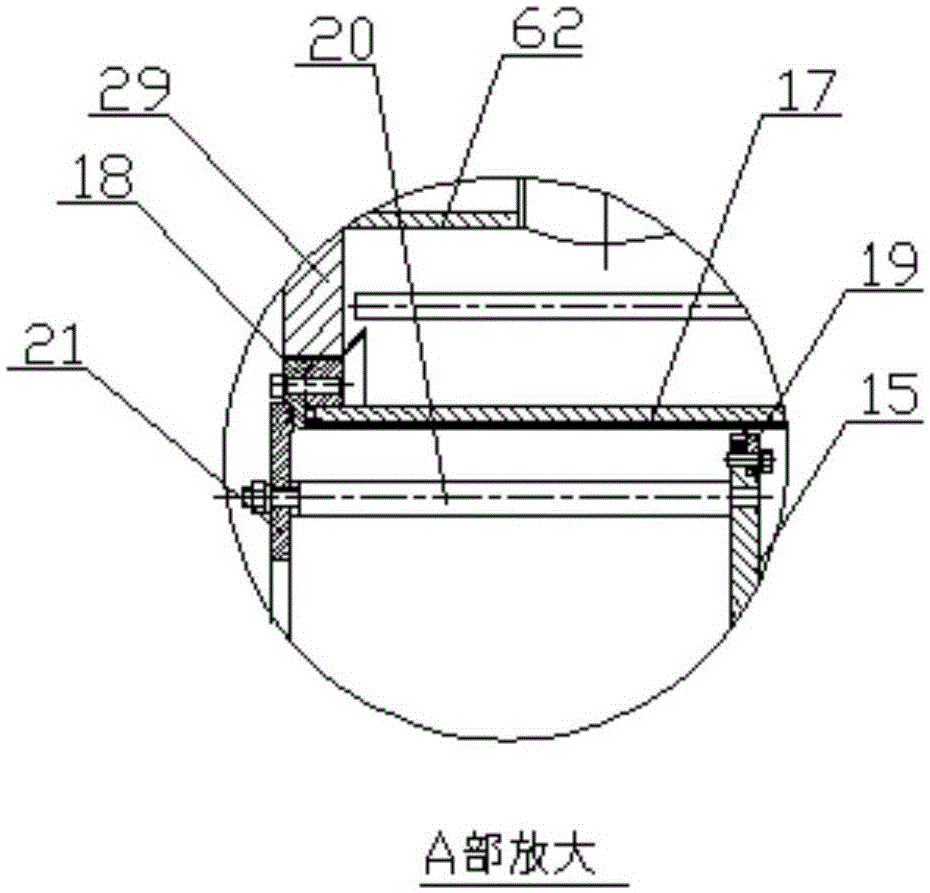
[0031] Such as Figure 1-3 As shown, an inverted bag centrifuge includes an installation base 1, and six shock absorbers 2 are provided on the lower surface of the installation base 1. The mounting base 1 is provided with a frame 3 , and the frame 3 is provided with a hollow main shaft 4 rotating around a horizontal axis, a drum assembly 5 , and a shell assembly 6 covering the drum assembly 5 . The main shaft 4 is rotatably arranged on the frame 3 through two sets of bearings. The frame 3 is provided with a rotary power device 7 for driving the main shaft 4 and the drum assembly 5 to rotate. Rotary power unit 7 comprises the driving pulley 71 that is arranged on the main shaft 4, the main motor 72 that is arranged on the frame 3, the driving pulley 73 that is connected with the output shaft of main motor 72, and the belt that connects drivin...


PUM


Abstract

The invention discloses a bag turning centrifugal machine. The bag turning centrifugal machine comprises a rack, a hollow spindle, a drum assembly, a shell body assembly and a rotation power device. A push rod penetrates in the spindle. The tail end of the push rod is connected with a bag turning power device. One end of the push rod penetrates through a through hole formed in a drum bottom to enter an inner cavity of a drum, and the end of the push rod is provided with a material pushing disk. The inner side of the drum wall is provided with a filter bag. One end of the filter bag is arranged at an outer edge opening of the drum. The other end of the filter bag is arranged on the material pushing disk. At least three support rods are evenly distributed on the material pushing disk in the circumferential direction. Material blocking rings are detachably arranged at the other ends of the support rods. The spindle drives the push rod to rotate synchronously through a driving mechanism. The shell body assembly comprises a rear end plate, a cylinder-shaped shell body and a front end cover. A water-seepage-proof and airproof telescopic cover is connected between the cylinder-shaped shell body and the front end cover. The lower end of the telescopic cover is provided with a material discharging hole. The front end cover is provided with a material feeding pipe. The rack is provided with a cover pushing hydraulic cylinder which drives the front end cover to move. The bag turning centrifugal machine is simple in structure, small in covering area, long in service life, and good in sealing performance.

Description

technical field [0001] The invention relates to an inverted bag centrifuge. Background technique [0002] Inverted bag centrifuges generally include a frame, a hollow main shaft and a drum assembly that are arranged on the frame and rotate around a horizontal axis, and a shell assembly that is placed outside the drum assembly. The rotary power device for the rotation of the drum assembly. The main shaft is pierced with a push rod that can slide along the axis of the main shaft. The bag turning power device that moves in the same direction is connected. The drum assembly includes the drum bottom connected to the main shaft and the drum wall arranged on the drum bottom. One end of the push rod enters the drum through the through hole set on the drum bottom. The inner cavity and this end is provided with a push plate; the inner side of the drum wall is provided with a filter bag, one end of the filter bag is set on the outer edge of the drum, the other end of the filter bag is...

Claims


Application Information

Patent Timeline
Patent Type & Authority Applications(China)
IPC IPC(8): B04B11/04B04B15/08B04B7/00B04B7/02B04B7/08B04B15/00B04B15/06
Inventor 刘鑫彦宋正华
Owner ZHANGJIAGANG ZHONGNAN CHEM MACHINERY
Why Eureka
Try Eureka