Led module three anti-paint spraying fixture and its use method

A technology of LED modules and spraying fixtures, applied in the direction of spraying devices, etc., can solve the problems of time-consuming adjustment, unusable fixtures, pollution of lamp surfaces, etc., and achieve the effect of reducing cleaning steps, reducing production costs, and saving production costs.

Active Publication Date: 2017-09-15
HUBEI PHILISENSE ELECTRONICS EQUIP
View PDF5 Cites 0 Cited by
  • Summary
  • Abstract
  • Description
  • Claims
  • Application Information

AI Technical Summary

Problems solved by technology

In the process of use, it is found that the three anti-paint fixtures cannot freely set the range of the card holder, and it is only suitable for one fixed product, not suitable for other products, and it takes a lot of time to adjust the size of the fixture before using the fixture , in addition, the screws of the fixture are easy to loosen during use, making the fixture unusable
Since the fixture fixes the front and rear sides of the module, when the conformal paint is sprayed, the conformal paint flows from the front and rear sides of the fixture to the lamp surface, causing the lamp surface to be unclean; due to the corresponding space reserved on the module PCB board , when spraying the conformal paint, a part of the conformal paint flows down from the space and pollutes the lamp surface, requiring a lot of manpower and time to clean the product, which leads to an increase in production costs
[0003] To sum up, the existing LED module three-proof paint spraying fixture has the disadvantages of long adjustment time, easy loosening, single applicable product, easy to pollute the module, and needs to be cleaned, which increases the cost.

Method used


Image

  • Led module three anti-paint spraying fixture and its use method
  • Led module three anti-paint spraying fixture and its use method
  • Led module three anti-paint spraying fixture and its use method

Examples


Embodiment Construction

[0023] The present invention will be further described in detail below in conjunction with the accompanying drawings and specific embodiments.

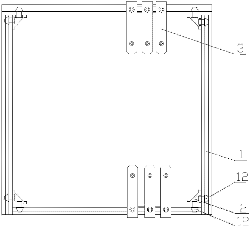
[0024] The LED module conformal paint spraying fixture proposed by the present invention includes:

[0025] Four crossbeams 1, four crossbeams 1 are connected successively to form a closed rectangle, the four sides of the crossbeam 1 are respectively provided with grooves 4 adapted to the head of the bolt; the outside of the groove 4 is provided with a channel 6 adapted to the shaft of the bolt , the diameter of the channel 6 is smaller than the diameter of the groove 4;

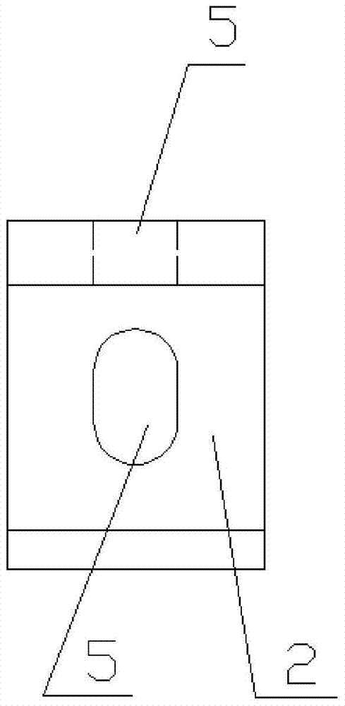
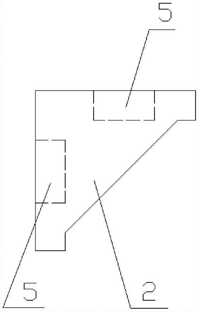
[0026] The four corner codes 2 are respectively provided with holes 5 for passing through bolt shafts on the vertically adjacent two sides of the corner codes 2;

[0027] Several sets of support frames 3, the support frames 3 are relatively arranged on two opposite beams 1, the support frames 3 include a frame body 7, and a handle 8 arranged on one side of the fram...


PUM


Abstract

The invention relates to an L ED module three-proofing paint spraying clamp and an application method thereof; the clamp comprises four crossbeams connected in sequence to form a sealed rectangle; four sides of the crossbeams are respectively provided with a groove and a channel outside the groove; the clamp also comprises four corner connectors, and two adjacent edges of the corner connector are provided with holes; a plurality of support racks are relatively arranged on two opposite crossbeams, and the support rack comprises a rack body, and a handle and a boss arranged on the rack body; the center of the handle is provided with a hole; the boss is provided with a positioning rod; bolts movably connect the four crossbeams in a whole body through the four corner connectors, and movably connect the support racks on the crossbeams; the method can adjust positions of the crossbeams and support racks, so the positioning rods on the support racks can fix positioning holes on the module; when four positioning holes of the module are fixed by the positioning rods, spray paint work can be carried out on the module. An existing clamp is long in adjusting time, easy to loosen, single in usage product, and can pollute the module; the L ED module three-proofing paint spraying clamp can solve the said problems, and simple and easy in operation method.

Description

technical field [0001] The invention relates to the technical field of LED processing, in particular to an LED module three-proof paint spraying fixture and a use method thereof. Background technique [0002] The LED module is a product composed of light-emitting diodes arranged together according to certain rules and packaged together, plus waterproof treatment. The LED module can play the role of dustproof, moisture-proof, corrosion-proof, anti-aging and so on by spraying three anti-paint, so as to improve the service life of the product. The currently used three-proof paint fixture is generally a back-shaped structure made of bakelite. The front and rear sides of the module to be sprayed with three-proof paint are stuck in the fixture by moving the front and rear two bakelite with wave grooves. Then spray the three anti-paint. In the process of use, it is found that the three anti-paint fixtures cannot freely set the range of the card holder, and it is only suitable for...

Claims


Application Information

Patent Timeline
Patent Type & Authority Patents(China)
IPC IPC(8): B05B13/02
CPCB05B13/025
Inventor 谈辉
Owner HUBEI PHILISENSE ELECTRONICS EQUIP
Why Eureka
Try Eureka