Single-coordinate small-stroke feeding power box
A small-stroke, single-coordinate technology, which is applied in the direction of driving devices, other manufacturing equipment/tools, drilling/drilling equipment, etc., can solve the problems of inability to fully automatic production online, low equipment reliability, slow production pace, etc., to achieve Compact structure, fast electrical response, and good equipment rigidity
- Summary
- Abstract
- Description
- Claims
- Application Information
AI Technical Summary
Problems solved by technology
Method used
Image
Examples
Embodiment 1
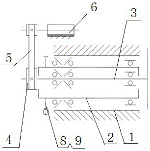
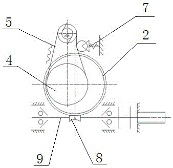
[0024] This embodiment provides a single coordinate small stroke feed power box, refer to figure 1 and figure 2 , including the power box 1 installed on the frame, the inside of the power box 1 is equipped with an eccentric sleeve 2 through a bearing, the main shaft 3 is installed in the eccentric sleeve 2 through a bearing, one end of the main shaft 3 is connected with a large pulley 4, and the large belt The wheel 4 is connected to the power source 6 through the belt 5 (the power source here can be a motor, or a hydraulic cylinder and other equipment that can provide power) to obtain power; the eccentric sleeve 2 is equipped with a power rotation drive mechanism, the The power rotation drive mechanism is connected to the outer wall of the eccentric sleeve 2 to drive the eccentric sleeve 2 to rotate; a flexible tensioning mechanism 7 is installed beside the belt 5, and the flexible tensioning mechanism 7 is in contact with the belt 5 to tension the belt 5 .
[0025] In thi...
Embodiment 2
[0029] On the basis of embodiment 1, this embodiment is further described, referring to figure 1 and figure 2 , the power rotation drive mechanism here includes a transmission worm gear 8 that engages with the outer wall of the eccentric sleeve 2 to transmit power and a transmission worm 9 installed in cooperation with the transmission worm gear 8 , and the transmission worm 9 is arranged perpendicular to the axial direction of the eccentric sleeve 2 .
[0030] Use the servo motor to drive the transmission worm 9 to rotate. Due to the interaction between the transmission worm 9 and the transmission worm 8, the transmission worm 9 rotates and the transmission worm 8 rotates in a direction perpendicular to the transmission worm 9, and then the transmission worm 9 drives the eccentric sleeve 2 to perform Turn to realize the rotation of the eccentric sleeve 2.
[0031] Similarly, the power rotation driving mechanism here can also be a gear pair mechanism or a lead screw nut pair...
Embodiment 3
[0033] In the above two embodiments, since the position of the main shaft 3 relative to the position of the power box 1 changes, the center distance of the belt pair of the belt 5 changes accordingly. Here, the belt 5 is a V-belt or a toothed synchronous belt, so the belt drive Auxiliary will be provided with flexible tensioning mechanism 7, the reliable tensioning of keeping belt. In this example, if figure 2 As shown, the flexible tensioning mechanism 7 includes a tensioning wheel that interferes with and acts on the belt 5, the tensioning wheel is connected with a spring expansion part, and the other end of the spring expansion part is fixed on the frame.
[0034] In this structure, the spring expansion part is a structural part with a specific force. According to the tension requirements of the belt, an appropriate spring is selected to realize the structural function. The tension pulley is close to the belt, making the belt tighter; if the belt becomes tighter as the po...
PUM
 Abstract
Description
Claims
Application Information
 - R&D
- Intellectual Property
- Life Sciences
- Materials
- Tech Scout
- Unparalleled Data Quality
- Higher Quality Content
- 60% Fewer Hallucinations
Browse by: Latest US Patents, China's latest patents, Technical Efficacy Thesaurus, Application Domain, Technology Topic, Popular Technical Reports.
© 2025 PatSnap. All rights reserved.Legal|Privacy policy|Modern Slavery Act Transparency Statement|Sitemap|About US| Contact US: help@patsnap.com


