Electric-driven type mechanical hand claw

A manipulator claw, electric technology, applied in manipulators, program-controlled manipulators, chucks, etc., can solve the problems of high cost, complexity, and impracticality of gripping light objects, and achieve the effect of simple structure setting and good gripping effect.

Inactive Publication Date: 2015-12-02
JIANGSU HUAAN SCI RES DEVICES
View PDF0 Cites 6 Cited by
  • Summary
  • Abstract
  • Description
  • Claims
  • Application Information

AI Technical Summary

Problems solved by technology

[0003] Traditional manipulators that use a pair of manipulator claws to realize opening and closing are often driven by cylinders. However, the structural design of motor-driven manipulator claws is more complicated and the cost will be higher. It is not practical f

Method used


Image

  • Electric-driven type mechanical hand claw
  • Electric-driven type mechanical hand claw

Examples


Example Embodiment

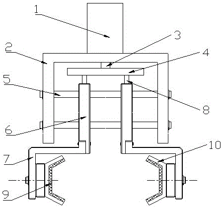
[0018] like figure 1 and figure 2 As shown, the present invention discloses an electric manipulator gripper, comprising a three-phase asynchronous motor 1 , a mounting plate 2 arranged at the lower end of the motor, and an actuator connected to the motor shaft 3 .

[0019] The mounting plate 2 is N-shaped and includes an upper top plate and two side plates, the middle of the upper top plate is fixedly connected to the three-phase asynchronous motor 1, and an actuator is arranged in the cavity at the lower end.

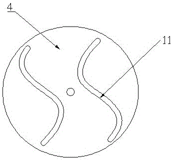
[0020] The actuator includes a rotating plate 4 connected with the motor shaft 3, a pair of parallel guide posts 5 arranged at the lower end of the rotating plate 4, a pair of sliding blocks 6 inserted into the pair of parallel guide columns 5, and a pair of sliding blocks arranged on the pair of sliding blocks. 6. A pair of V-shaped claws 10 at the lower end; the rotating plate 4 is circular, the middle part is fixed on the motor shaft 3, and a pair of symmetrical S...


PUM


Abstract

The invention relates to an electric-driven type mechanical hand claw. The electric-driven type mechanical hand claw comprises a motor, an installing plate and an actuating mechanism, wherein the installing plate is arranged at the lower end of the motor; the actuating mechanism is connected with a motor shaft; the installing plate is N-shaped; the middle part of the upper end of the installing plate is fixedly connected with the motor; the actuating mechanism is arranged in a cavity in the lower end of the installing plate; the actuating mechanism is formed by a rotating plate which is connected with the motor shaft, a pair of parallel guiding columns which are arranged at the lower end of the rotating plate, a pair of sliding blocks which are matched with the parallel guiding columns in an inserting way and a pair of V-shaped claws; the rotating plate is circular; the middle part of the rotating plate is fixedly arranged on the motor shaft; a pair of S-shaped through grooves of which the circle centers are symmetrical are formed in the rotating plate; two through holes which are used for enabling the parallel guiding columns to be inserted to be matching are oppositely formed in the pair of sliding blocks; the middle parts of the upper ends of the sliding blocks are provided with a pair of parallel vertical columns which are inserted into the S-shaped through grooves in a matching way; the lower ends of the sliding blocks are fixedly connected with the pair of V-shaped claws which are oppositely arranged. The electric-driven type mechanical hand claw disclosed by the invention has the advantages that the electric-driven type mechanical hand claw is driven by adopting the motor and slides in the through grooves in the rotating plate through the parallel vertical columns at the upper ends of the sliding blocks, so that opening and closing of the V-shaped claws are realized, and the structure setting is simple and reasonable.

Description

technical field [0001] The invention relates to a manipulator, in particular to an electric manipulator. Background technique [0002] A manipulator is an automatic machine that simulates human operation. It can grab, carry objects or handle tools according to a fixed program to complete certain specific operations. The application of manipulators can replace people in monotonous, repetitive or heavy manual labor, realize mechanization and automation of production, replace people in manual operations in harmful environments, improve working conditions, and ensure personal safety. Therefore, it is widely used in machinery manufacturing, metallurgy, electronics. and other industries. [0003] The traditional manipulators that use a pair of manipulators to open and close are often driven by cylinders, while the structure design of the motor-driven manipulators is more complicated and the cost will be high. It is not practical for gripping light objects, so it is urgent to deve...

Claims


Application Information

Patent Timeline
IPC IPC(8): B25J9/12B25J15/08
CPCB25J9/12B25J15/08
Inventor 张跃兰
Owner JIANGSU HUAAN SCI RES DEVICES
Why Eureka
Try Eureka