
Vibration sensing optical cable and use method thereof

A sensing optical cable, sensing optical fiber technology, applied in the direction of light guide, optics, optical components, etc., can solve the long-term reliability of the sensing optical cable is not high, can not be fully satisfied, the false alarm rate is high, achieve easy long-distance multi-point Distributed measurement, simple and reasonable structure setting, fast and accurate positioning

Inactive Publication Date: 2016-05-04
武汉烽理光电技术有限公司
View PDF4 Cites 10 Cited by
  • Summary
  • Abstract
  • Description
  • Claims
  • Application Information

AI Technical Summary

Problems solved by technology

The positioning and analysis of multi-point intrusion by ODTR technology is complicated, and it is difficult to accurately locate
The perimeter technology based on the principle of interference is a phase modulation type, so it is sensitive to the polarization state of the incident light and the influence of the outside world, the false alarm rate is high, and accurate positioning is difficult
In order to solve the problem of precise positioning, some institutions have developed fiber optic perimeter security systems based on fiber gratings. However, due to the use of high reflectivity (strong) grating welding to prepare sensing cables, due to the limitation of the bandwidth of the light source, multiplexing on one fiber The limited number of gratings limits the distance or range of detection by the system
In addition, since the sensing optical cable is prepared by welding the grating, the tensile strength of the optical fiber is greatly reduced, and the long-term reliability of the sensing optical cable is not high, which cannot fully meet the requirements of the actual application for the fiber grating vibration sensing optical cable.
It can be seen that the fiber grating vibration sensing cable needs to solve the problems of low grating preparation efficiency, small number of gratings, low fiber strength, large loss, poor reliability of the optical cable, and complex optical cable structure in the grating array.

Method used

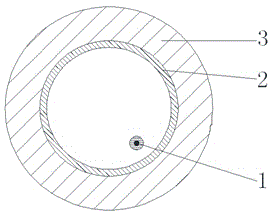
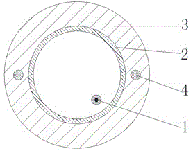
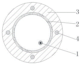

Image

  • Vibration sensing optical cable and use method thereof
  • Vibration sensing optical cable and use method thereof
  • Vibration sensing optical cable and use method thereof

Examples


Embodiment 3

[0031] The cable forming process of the fiber grating array sensing optical cable of the present invention (taking embodiment 3 as an example) is as follows:

[0032] During the cabling process, the optical fiber is released in the form of active pay-off with small tension. First, a reinforcement is longitudinally wrapped around the optical fiber, with a diameter of preferably 2-5mm, and then the steel wire is released. The sheath is made of polyvinyl chloride, and then the sheath is stretched in the cold water tank by selecting the appropriate speed of the traction wheel. At this time, the longitudinal package reinforcement is stretched together, and the optical fiber is in the loose sleeve structure without traction. round effect, accumulating longer fibers in the sheath. Then wait for the sheath to pass through the traction wheel, the longitudinal sheath reinforcement and the sheath recover elastically, and the length is shortened, so that the optical fiber in the loose she...


PUM


Abstract

The invention relates to a vibration sensing optical cable and a use method thereof. The vibration sensing optical cable includes an outer sheath and a sensing optical fiber, wherein the sensing optical fiber is laid in the outer sheath. The vibration sensing optical cable is characterized in the sensing optical fiber is an identical Fiber Bragg Grating array optical fiber which is engraved into gratings directly online in fiber drawing; the reflectivity of the gratings ranges from -20dB to -70dB; a metal armoring layer is arranged in the outer sheath; the sensing optical fiber is loosely laid in the metal armoring layer; and the outer sheath is an integrated outer sheath which is formed through one-step extrusion molding. According to the vibration sensing optical cable of the invention, no welding points exist on the optical fiber, vibration signals between any one pair of adjacent gratings on the optical fiber can be detected and can be accurately and stably positioned, and long-distance multi-point distributed measurement can be carried out with easiness. The vibration sensing optical cable can be multiplexed so as to form a sensing network. The optical cable has the advantages of high strength, small transmission loss, high consistency of the gratings, simple and reasonable structure, strong tensile and compressive mechanical properties, fast and accurate positioning and high repeatability of measurement results.

Description

technical field [0001] The invention relates to a vibration sensing optical cable and a using method thereof, belonging to the technical field of optical fiber sensing. Background technique [0002] One use of fiber optic vibration sensing cables is in the development of fiber optic perimeter security systems. The perimeter security system refers to the defense system that guards against the border of a certain area or alarms when the border is invaded by foreign things. Perimeter security technology and products were initially mainly used for border security protection in some important military areas, and now they have been extended to national borders, airport perimeters, industrial park perimeters, residential area perimeters, high-speed rail lines, oil and gas transmission pipelines, power transmission lines, etc. , the market demand for perimeter security technology and products continues to expand. Among the perimeter security products, the electric perimeter securi...

Claims


Application Information

Patent Timeline
Patent Type & Authority Applications(China)
IPC IPC(8): G01H9/00G02B6/44
CPCG01H9/004G02B6/443G02B6/4432
Inventor 余海湖徐一旻郭会勇李小甫许儒泉姜德生
Owner 武汉烽理光电技术有限公司
Learn More