
Hydraulic fast forging unit adopting superposed oil supply of hydraulic pumps and high-pressure accumulators

A high-pressure accumulator and hydraulic oil technology, which is applied to the accumulator device, the drive device of the press and the forging press, etc., can solve the problems of no-load energy consumption, large power waste, and unreasonable hydraulic pump configuration. , to achieve the effect of reasonable resource allocation, avoiding energy waste and reducing energy consumption

Active Publication Date: 2017-03-29
ZHONGJUXIN OCEAN ENG EQUIP CO LTD
View PDF8 Cites 8 Cited by
  • Summary
  • Abstract
  • Description
  • Claims
  • Application Information

AI Technical Summary

Problems solved by technology

[0015] The purpose of the present invention is to provide a hydraulic fast forging unit in which a hydraulic pump and a high-pressure accumulator are superimposed to supply oil, so as to solve the technical problems of unreasonable configuration of the hydraulic pump of the traditional hydraulic fast forging unit, resulting in high energy consumption and large waste of electric energy under no load

Method used


Image

  • Hydraulic fast forging unit adopting superposed oil supply of hydraulic pumps and high-pressure accumulators

Examples


Embodiment Construction

[0048] The present invention will be further explained below in conjunction with accompanying drawing:

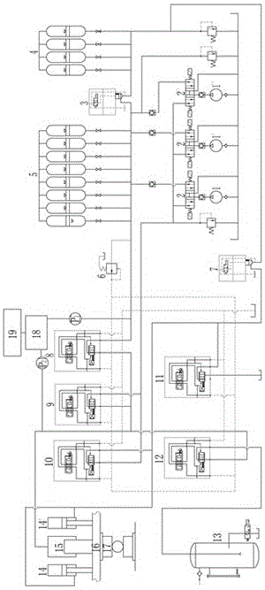
[0049] as attached figure 1 As shown, the main hydraulic cylinder 15 is a plunger hydraulic cylinder, and the forging hammer head 17 of the hydraulic fast forging unit is connected to the plunger of the main hydraulic cylinder 15 through the movable beam 16, and when the plunger is filled with hydraulic oil, the forging hammer head 17. Empty stroke descending; the single-out rod return hydraulic cylinders 14, 14' are placed on both sides of the main hydraulic cylinder 15, and the single-out rod in it is linked with the forging hammer head 17 through the movable beam 16. When the rod chamber is filled with hydraulic pressure The forging hammer head 17 realizes the return stroke when the oil is oily; there are multiple high-pressure accumulators, and the multiple accumulators are divided into Group A high-pressure accumulator 5 and Group B high-pressure accumulator 4; the con...


PUM


Abstract

A hydraulic fast forging unit adopting superposed oil supply of hydraulic pumps and high-pressure accumulators comprises a forging and pressing hammer, a main hydraulic cylinder, single-rod return stroke hydraulic cylinders, the main hydraulic pumps, the high-pressure accumulators, a medium-pressure accumulator, an oil tank and a valve control system. During the return stroke of the forging and pressing hammer, hydraulic oil in the single-rod return stroke hydraulic cylinders is supplied by the main hydraulic pumps, and stored oil in the main hydraulic cylinder is drained into the medium-pressure accumulator; during the idle-stroke fast dropping of the forging and pressing hammer, hydraulic oil in the main hydraulic cylinder is supplied by the medium-pressure accumulator independently, stored oil in the single-rod return stroke hydraulic cylinders is drained into the oil tank, and the main hydraulic pumps supply oil to the high-pressure accumulators; during rolling of the forging and pressing hammer, hydraulic oil in the main hydraulic cylinder is supplied by the main hydraulic pumps and the high-pressure accumulators in a superposed supply manner; during execution of the fast forging manner, hydraulic oil in the main hydraulic cylinder is supplied by the main hydraulic pumps and part of the high-pressure accumulators in a superposed supply manner, and during the fast return stroke, hydraulic oil of the single-rod hydraulic cylinder is supplied by the other part of the high-pressure accumulators; and control hydraulic oil of the valve control system is supplied by the high-pressure accumulators. The hydraulic fast forging unit has the beneficial effects of being simple in structure, small in equipment investment, high in energy utilization rate and the like.

Description

technical field [0001] The invention relates to a hydraulic rapid forging unit, in particular to a hydraulic rapid forging unit using a hydraulic pump and a high-pressure accumulator as superimposed power sources, and belongs to the technical field of hydraulic transmission. Background technique [0002] The main movements that the hydraulic fast forging unit needs to complete on the press are divided into: 1. The hammer head rises (return); 2. The hammer head falls, and the falling movement process is divided into: a. Empty rapid drop; Traditional hydraulic fast forging units are usually equipped with multiple high-power main hydraulic pumps and low-pressure accumulators as the power source of the hydraulic system to provide the required power for the return stroke of the hammer head and the rapid fall and rolling of the hammer head in the empty space. At the same time, the hydraulic system A control pump is also specially set up to provide power oil for controlling the ope...

Claims


Application Information

Patent Timeline
Patent Type & Authority Applications(China)
IPC IPC(8): F15B1/02F15B1/033B21J9/12
CPCB21J9/12F15B1/024F15B1/0275F15B1/033F15B2211/212B30B15/161B30B15/22B30B15/163
Inventor 张连华马海军王季
Owner ZHONGJUXIN OCEAN ENG EQUIP CO LTD
Learn More