Aircraft hardpoint sealing mechanism driven by motors

A motor-driven, point-sealing technology, which is applied in the direction of aircraft accessories, etc., can solve the problems that the sealing plate cannot be closed, is close to the dead point, and has a large plane area, and achieves the effect of simple structure and convenient use

Inactive Publication Date: 2015-12-02
NORTHWESTERN POLYTECHNICAL UNIV
View PDF5 Cites 2 Cited by
  • Summary
  • Abstract
  • Description
  • Claims
  • Application Information

AI Technical Summary

Problems solved by technology

The disadvantage of this method is that after the pylon is thrown away, there is no flap to seal the opening in the skin at the hardpoint, which is detrimental to the aerodynamic and stealth performance of the aircraft
Invention patent 201410279843.X introduces a spring-driven sealing mechanism, which has three main disadvantages: (1) This solution relies on the dead point of the four-bar mechanism to realize automatic closing, but the opening position is too close to the dead point, It is easy to cause the fault that the sealing plate cannot be closed; (2) After the sealing mechanism is opened, the two sealing plates are respectively stored in the casing on both sides, so it is necessary to reserve enough space in the casing, resulting in a large plane area of ​​the entire sealing mechanism , it is necessary to reserve a large opening on the skin, and the skin is an important force transmission structure of the aircraft, and a large opening will have an adverse effect on the structural strength of the aircraft; (3) After the sealing mechanism is installed, the entire sealing mechanism is fully exposed Outside the theoretical shape of the aircraft, it will cause a certain degree of damage to the aircraft's aerodynamics and stealth shape

Method used


Image

  • Aircraft hardpoint sealing mechanism driven by motors
  • Aircraft hardpoint sealing mechanism driven by motors
  • Aircraft hardpoint sealing mechanism driven by motors

Examples


Embodiment Construction

[0020] In order to make the technical means, creative features, goals and effects achieved by the present invention easy to understand, the technical solutions in the embodiments of the present invention will be clearly and completely described below in conjunction with the accompanying drawings in the embodiments of the present invention.

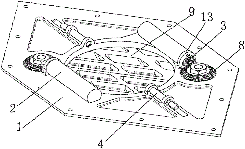
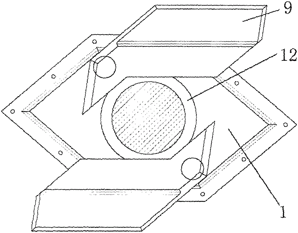
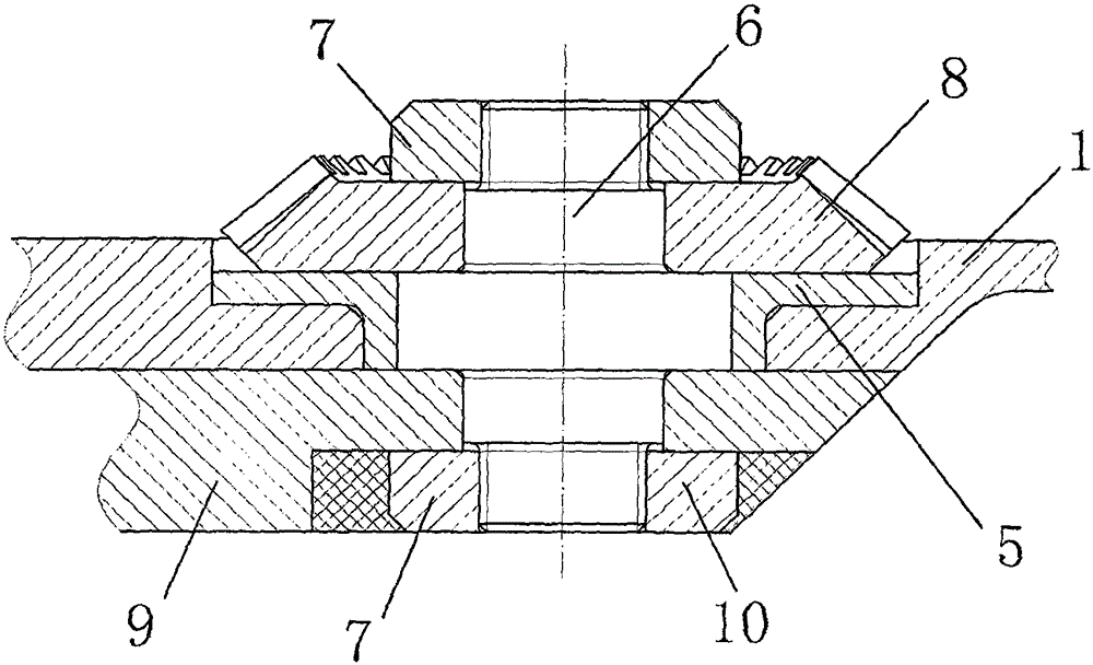
[0021] see figure 1 , the specific embodiment is realized by adopting the following technical scheme, which includes a housing 1, which is provided with a hanger hole 12, and the outer bottom surface of the housing 1 is respectively equipped with a sealing plate 9 that can rotate and cooperate with it. The sealing plate 9 is located on both sides of the hanger hole 12, and the inner surface of the housing 1 is equipped with a stepper motor 2 that drives the sealing plate 9 to rotate and a through-beam infrared sensor 4 located on both sides of the hanger hole 12;

[0022] The stepping motor 2 is fixed on the casing 1 through the base 13, a...


PUM


Abstract

The invention discloses an aircraft hardpoint sealing mechanism driven by motors. The aircraft hardpoint sealing mechanism comprises a casing (1), wherein a hanging frame hole (12) is formed in the casing (1), and two sealing plates (9) matched with the casing (1) in a rotating manner are mounted on the bottom surface of the outer sides of the casing (1) respectively and positioned on two sides of the hanging frame hole (12) respectively; a step motor (2) driving the sealing plates (9) to rotate and two opposite-transmitting type infrared sensors (4) positioned on two sides of the hanging frame hole (12) respectively are mounted on the inner side surface of the casing (1). The aircraft hardpoint sealing mechanism disclosed by the invention is simple in structure and convenient to use, when a hanging frame is mounted, the sealing plates are opened through a switch by ground staff, then the sealing plates are held in an open state, and when the hanging frame is released, the sealing mechanism is automatically closed, so that the aircraft hardpoint sealing mechanism is relatively convenient to use; because space for the sealing plates does not need to be reserved in the inner part of the casing, and plan view sizes of the sealing mechanism and a corresponding skin opening are small and slightly greater than sizes of the hanging frame, so that influence on the structural strength of the aircraft is small.

Description

technical field [0001] The invention relates to the field of aircraft structure design, in particular to a motor-driven aircraft external storage point sealing mechanism. Background technique [0002] In order to increase the range and ammunition load of modern stealth aircraft, and increase the flexibility of carrying ammunition and combat missions, it is necessary to use external hardpoints under the wings or fuselage to carry various ammunition, pods, and auxiliary fuel tanks. In the process of performing combat missions, in order to ensure maneuverability and stealth performance, before entering the theater, the auxiliary fuel tank needs to be thrown away together with the pylon. In addition, after the aircraft has launched the external ammunition, it is also necessary to throw away the pylon to reduce the radar reflection area of ​​the aircraft and restore a clean aerodynamic shape. In order to install the pylon, an opening is left in the skin at the external hardpoint...

Claims


Application Information

Patent Timeline
Patent Type & Authority Applications(China)
IPC IPC(8): B64C1/14
Inventor 金朋孙中超喻天翔庄新臣宋笔锋
Owner NORTHWESTERN POLYTECHNICAL UNIV
Why Eureka
Try Eureka