
A kind of power generation toilet water tank and toilet water tank power generation method

A water tank and toilet technology, which is applied to flushing equipment with water tanks, water supply devices, engine components, etc., can solve the problems of slow water intake, flow restriction, and small space of the water inlet valve, and achieves increased power generation, improved stability, Protective effect

Active Publication Date: 2017-03-01
JOMOO KITCHEN & BATHROOM
View PDF6 Cites 0 Cited by
  • Summary
  • Abstract
  • Description
  • Claims
  • Application Information

AI Technical Summary

Problems solved by technology

[0004] The disadvantage of the above utility model is that the turbine of the small hydroelectric generator is installed on the water inlet channel from the water supply pipe of the water tank to the water outlet of the water inlet valve, the space for the installation of the generator is small, and the flow rate is limited by the caliber of the water inlet pipe
Moreover, the space of the water inlet channel is limited, and multiple generators cannot be installed. If multiple generators are installed, the normal water intake of the water inlet pipe will be affected, and the water inlet valve will enter slowly.

Method used


Image

  • A kind of power generation toilet water tank and toilet water tank power generation method
  • A kind of power generation toilet water tank and toilet water tank power generation method

Examples


Embodiment Construction

[0023] The present invention will be further described in detail below in conjunction with the accompanying drawings and embodiments.

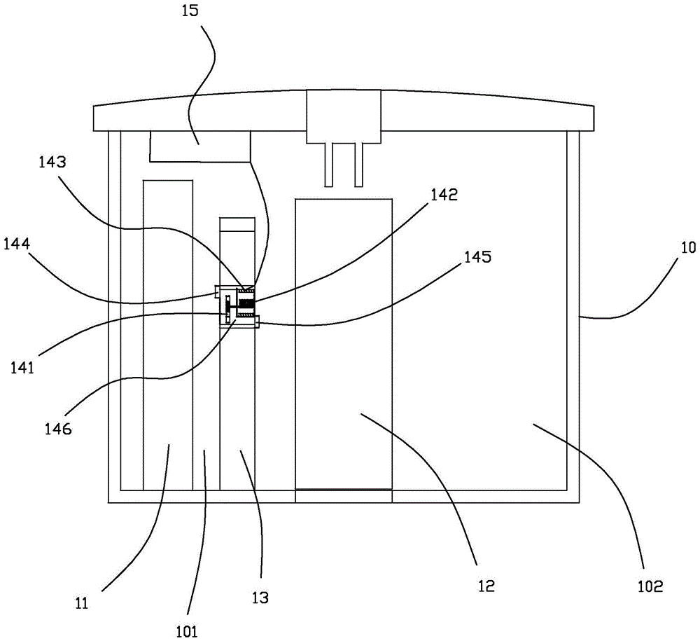
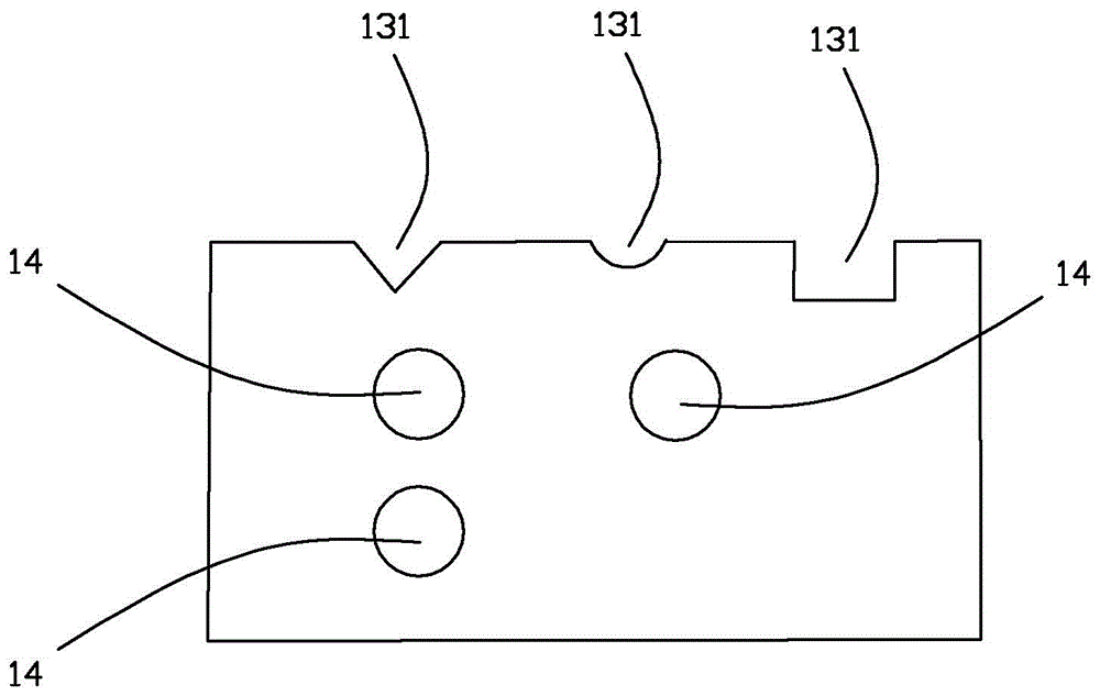
[0024] The invention provides a power generating toilet water tank, such as figure 1 As shown, it includes a water tank 10, a water inlet valve 11, and a water outlet valve 12. A partition wall 13 extending from bottom to top is arranged in the water tank 10, and the partition wall 13 separates the water tank 10 into a water inlet tank 101 and a water outlet tank that are not connected at the bottom. Body 102, water inlet valve 11, water outlet valve 12 are arranged in water inlet box body 101, water outlet box body 102 respectively; At least one water current generator 14 is arranged in the partition wall 13, and the water inlet 144 of water flow generator 14 is arranged on the water inlet On the side of the box body 101 , the water outlet 145 of the water flow generator 14 is arranged on the side of the water outlet box body 102 ; the water ...


PUM


Abstract

The invention relates to a power generation toilet water tank and a power generation method of the toilet water tank. The power generation toilet water tank is characterized in that a separating wall is arranged in the water tank, a mini type reservoir is formed, water flow generators are arranged in the separating wall, and power is generated by utilizing water pressure difference; the mini type reservoir is arranged in the water tank, so that the potential energy of water is enhanced, and the generated energy is increased; the water flow generators can be arranged on the separating wall at will, the arranging condition of the water flow generators on the separating wall is that the number of the water flow generators in the transverse direction and the longitudinal direction is respectively not less than one, power is generated by depending on a single water flow generator or in-parallel water flow generators, and the total power generation and the current stability are increased; the generated electric quantity can be transmitted into a built-in storage battery of the water tank through a wire, and the electric quantity of the storage battery can be used by an LED (Light Emitting Diode) lamp band or other mini type displays; a water inlet tank body is communicated with a water outlet tank body through a space above the separating wall, water in the water inlet tank body also flows to the water outlet tank body through the space above the separating wall, the situation that the liquid level of one of the water inlet tank body and the water outlet tank body is higher than or lower than the liquid level of the other one of the water inlet tank body and the water outlet tank body cannot be generated, and the stability of washing water volume is ensured.

Description

technical field [0001] The invention relates to water tank power generation technology, more specifically, to a toilet water tank for power generation and a method for generating power for the toilet water tank. Background technique [0002] The hydropower generation technology in the toilet water tank of the prior art only focuses on the water inlet 144 and the water inlet valve of the water tank, and fails to make full use of the space advantage in the water tank. [0003] For example, Chinese Utility Model Patent No. 200620085064.7 discloses a self-powered electric toilet water tank accessory, including a water inlet valve located at the water inlet of the water tank, an electric drain valve located at the water tank outlet, and at least one small hydraulic generator. The turbine of the generator is installed on the water inlet channel from the water inlet pipe of the water tank to the outlet of the water inlet valve, and the force bearing surface of its blade faces the w...

Claims


Application Information

Patent Timeline
Patent Type & Authority Patents(China)
IPC IPC(8): E03D1/00F03B13/00E03D1/012
Inventor 林孝发林孝山陈兴新陈财能丁祖雷
Owner JOMOO KITCHEN & BATHROOM
Learn More