Thermo-acoustic system driven by liquefied natural gas cold energy
A technology of liquefied natural gas and thermoacoustic system, applied in the field of thermoacoustic system, can solve the problems of low efficiency, large viscous resistance and high sound power loss of thermoacoustic engines, and achieves improving the utilization rate of cooling capacity, reducing viscous resistance, reducing sound The effect of power loss
- Summary
- Abstract
- Description
- Claims
- Application Information
AI Technical Summary
Problems solved by technology
Method used
Image

Examples
Embodiment 1
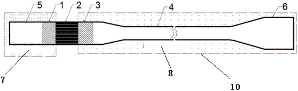
[0022] A thermoacoustic system driven by cold energy of liquefied natural gas, the thermoacoustic system is a standing wave thermoacoustic system, and its structure is as follows figure 1 As shown, the standing wave thermoacoustic system includes a hot-end gas storage 5, a hot-end heat exchanger 1, a regenerator 2, a cold-end heat exchanger 3, a resonant tube 4, and a cold-end gas storage 6 connected in sequence. The heater 1 and the hot-end gas storage 5 are arranged in the heat source 7, the cold-end heat exchanger 3, the resonant tube 4 and the cold-end gas storage 6 are provided with a jacket 10, and the jacket 10 is provided with a liquefied natural gas in and out. At the inlet and outlet, the liquefied natural gas cold source 8 is set in the jacket 10, the temperature of the heat source 7 is 30°C, and the temperature of the liquefied natural gas cold source 8 is -160°C;
[0023] Using the temperature difference between the hot end heat exchanger 1 and the cold end heat e...
Embodiment 2
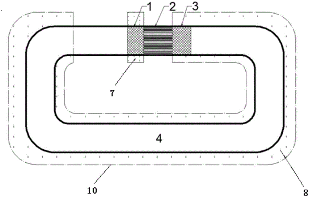
[0025] A thermoacoustic system driven by cold energy of liquefied natural gas, the thermoacoustic system is a traveling wave thermoacoustic system, and its structure is as follows figure 2 As shown, the traveling wave thermoacoustic system includes a hot-end heat exchanger 1, a regenerator 2, a cold-end heat exchanger 3, and a resonant tube 4 connected in sequence, and returns to the hot-end heat exchanger 1, and the hot-end heat exchanger 1 Set in the heat source 7, the cold end heat exchanger 3 and the resonant tube 4 are provided with a jacket 10 outside, and the jacket 10 is provided with an inlet and an outlet for the liquefied natural gas to enter and exit, and the liquefied natural gas cold source 8 is arranged in the jacket 10 , the temperature of the heat source 7 is 30°C, and the temperature of the LNG cold source 8 is -160°C;
[0026] Using the temperature difference between the hot end heat exchanger 1 and the cold end heat exchanger 3, a temperature gradient is e...
Embodiment 3
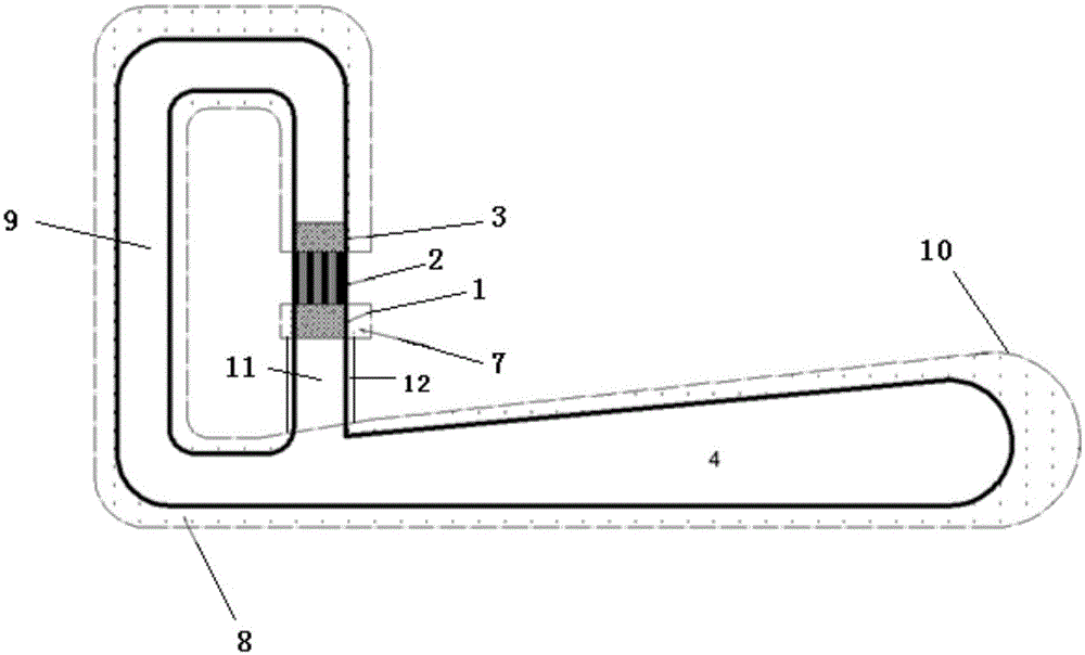
[0028] A thermoacoustic system driven by cold energy of liquefied natural gas. The thermoacoustic system is a traveling wave-standing wave hybrid thermoacoustic system. Its structure is as follows: image 3 As shown, the traveling wave-standing wave hybrid thermoacoustic system includes a thermal buffer tube 11, a hot end heat exchanger 1, a regenerator 2, a cold end heat exchanger 3, a feedback tube 9, and a resonance tube 4 connected in sequence. The buffer tube 11 is connected to the resonant tube 4, and the thermal buffer tube 11 is provided with an insulating tube 12 to ensure that the wall surface of the thermal buffer tube 11 is adiabatic. The hot end heat exchanger 1 is arranged in the heat source 7, and the cold end heat exchanger 3, feedback The pipe 9 and the resonant pipe 4 are provided with a jacket 10 outside, and the jacket 10 is provided with inlets and outlets for the entry and exit of liquefied natural gas. The cold source 8 of the liquefied natural gas is arr...
PUM
 Abstract
Description
Claims
Application Information
 - R&D
- Intellectual Property
- Life Sciences
- Materials
- Tech Scout
- Unparalleled Data Quality
- Higher Quality Content
- 60% Fewer Hallucinations
Browse by: Latest US Patents, China's latest patents, Technical Efficacy Thesaurus, Application Domain, Technology Topic, Popular Technical Reports.
© 2025 PatSnap. All rights reserved.Legal|Privacy policy|Modern Slavery Act Transparency Statement|Sitemap|About US| Contact US: help@patsnap.com