Differential screw hardness measuring device

A technology of differential screw and measuring device, which is applied in the direction of testing material hardness, etc. It can solve the problems of reduced screw transmission accuracy, reduced thread strength, and large volume, and achieves the effects of solving strength and service life, increasing reliability, and simple structure

Active Publication Date: 2015-12-02
SHENJAN TJANSIN TESTING INSTR KO LTD
View PDF8 Cites 8 Cited by
  • Summary
  • Abstract
  • Description
  • Claims
  • Application Information

AI Technical Summary

Problems solved by technology

[0003] Existing hardness measuring devices often adopt a lever loading method in providing test force. The problem with this method is that it is bulky and it is not convenient to be used as an independent working unit on an automatic measuring device.
[0004] Existing hardness measuring devices also adopt the hydraulic transmission loading method in providing test force. The problem with this method is that it is difficult to control the test force. The precise control of the test force requires a sophisticated and complex hydraulic servo control system. Manufacture and maintenance are more difficult
[0005] In terms of providing test force, existing hardness measuring devices also adopt servo motor drive, screw transmission and pressure sensor feedback loading methods. The problem with this method is that the transmission accuracy is greatly affected by the machining accuracy of the screw and nut.
[0006] In order to accurately measure the residual increment of indentation depth and calculate the hardness value based on the residual increment of indentation depth, existing hardness measuring devices need to be equipped with displacement measuring devices, such as dial indicators, screw micrometers, encoders or displacement sensors , among them, mechanical measurement methods such as dial indicators and spiral micrometers cannot automatically collect data and cannot be applied to automatic measurement devices
The use of an enco

Method used


Image

  • Differential screw hardness measuring device
  • Differential screw hardness measuring device
  • Differential screw hardness measuring device

Examples


Embodiment Construction

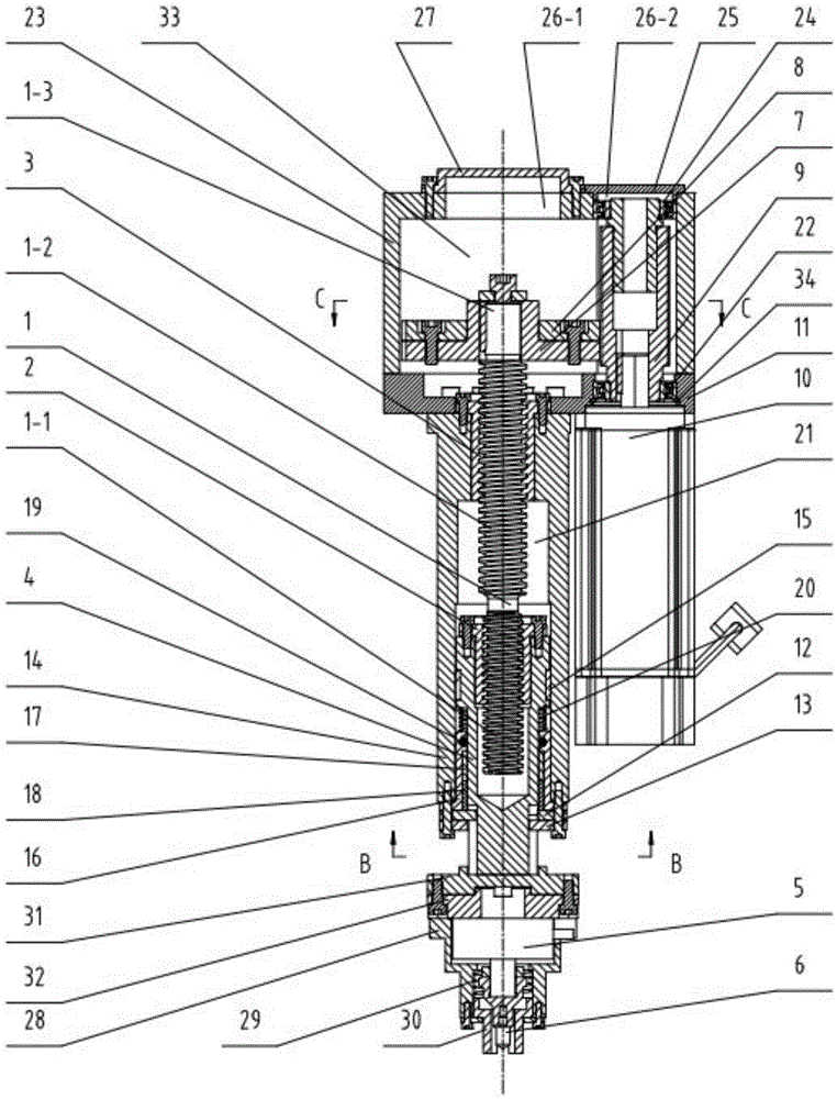
[0051] Specific embodiments of the present invention are provided below in conjunction with the accompanying drawings.

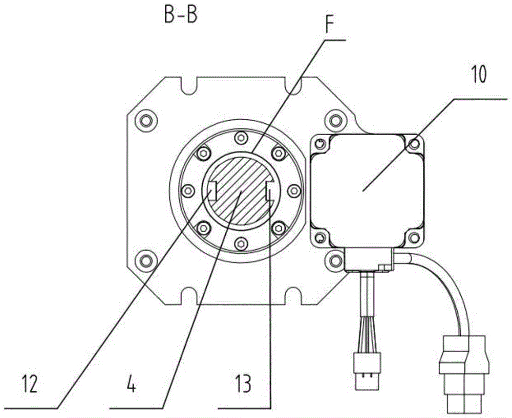
[0052] Such as figure 1 As shown, the present invention includes a force sensor 5, a pressure head 6 and a motor 10, and the lead of the first thread 1-1 at the lower end of the stud 1 is P 1 , the lead of the second thread 1-2 at the upper end of stud 1 is P 2 , there is a first nut 2 outside the first thread 1-1, the first nut 2 is fixedly connected to the upper end of the inner sleeve 4, and the lower end of the inner sleeve 4 is fixedly connected to the upper end of the force sensor 5 through the connection plate 31 and the transition plate 32 , the lower end of the force sensor 5 is fixedly connected with the pressure head 6, and there is a second nut 3 outside the second thread 1-2, and the second nut 3 is fixedly connected with the upper end of the outer sleeve 14, and the stud 1, the first The nut 2 and the second nut 3 form a differential screw, s...


PUM


Abstract

The invention discloses a differential screw hardness measuring device, and overcomes the problem that the conventional hardness measuring device cannot be compact in structure, long in service life, accurate in measurement and low in cost at the same time. The differential screw hardness measuring device is characterized in that: the lead of a first thread at the lower end of a double-thread screw is P1, the lead of a second thread at the upper end is P2, and the P1 minus the P2 equals to delta P which is a relatively small numerical value; a first nut is arranged outside the first thread; the first nut is fixedly connected with the upper end of an inner sleeve; the lower end of the inner sleeve is fixedly connected with a force sensor; a second nut is arranged outside the second thread; the second nut is fixedly connected with the upper end of an outer sleeve; a tiny displacement distance is formed at the meshing position of a first driven gear and a second driven gear with a driving gear. The differential screw hardness measuring device has the following benefits: relatively small displacement can be generated through adopting a screw with a relatively large lead, so that the contradiction among accurate measurement of indentation depth residual increment, strength of screws and nuts and service life is solved; besides, a displacement sensor is avoided, so that the whole system is simpler in structure, low in cost and high in reliability.

Description

technical field [0001] The invention belongs to the technical field of hardness detection equipment, in particular to a differential screw hardness measurement device. Background technique [0002] At present, the hardness measuring devices that use the static test method to detect the hardness of metal materials and products often use three detection methods: Brinell, Rockwell and Vickers. In principle, a standard indenter with high hardness is used Press into the surface of the sample with the specified test force, measure the geometric dimensions of the indentation after the test force is removed, and calculate the hardness value according to the measurement results. The Brinell hardness test method and the Rockwell hardness test method are both for pressure measurement. First add the initial test force F 0 , plus the main test force F 1 , at the total test force F 0 +F 1 Under the action, the indenter is pressed into the surface of the sample, and the main test force...

Claims


Application Information

Patent Timeline
IPC IPC(8): G01N3/42
Inventor 张凤林杨兵锋
Owner SHENJAN TJANSIN TESTING INSTR KO LTD
Why Eureka
Try Eureka