Gate driving method and structure
A gate drive and bias current technology, applied to instruments, static indicators, etc., can solve the problem of increased panel power consumption
- Summary
- Abstract
- Description
- Claims
- Application Information
AI Technical Summary
Problems solved by technology
Method used
Image
Examples
Embodiment Construction
[0021] Now, a detailed reference is provided to the embodiments of the present invention, and examples thereof are illustrated in the drawings, and the same numbers in the drawings all represent the same elements. To explain the present invention, the following embodiments will be described with reference to the drawings.
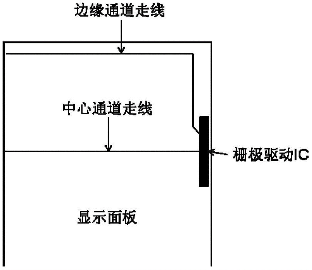
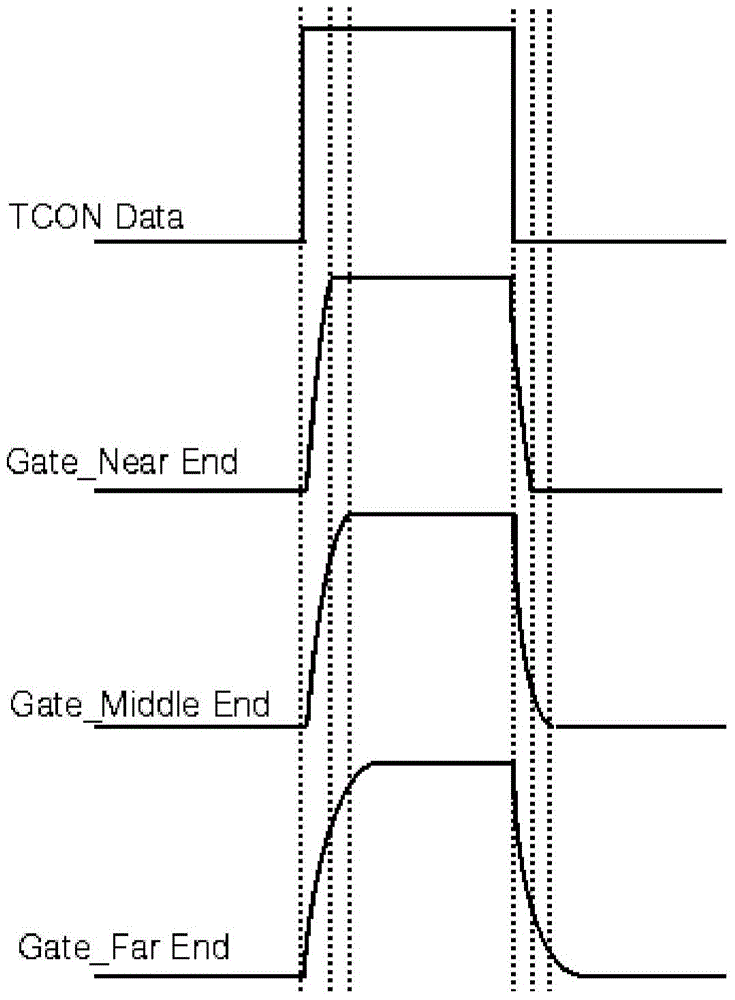
[0022] The low-power gate IC topology to be protected by the present invention is applied to an existing liquid crystal display panel, where the fan-out resistance of the gate drive IC at the edge of the panel is small, and the fan-out resistance of the gate drive IC at the center of the panel Larger structure. Due to this relationship of IC fan-out resistance, it is sufficient to drive the gate operation by providing a lower output bias current near the center of the panel.
[0023] Figure 4 Shows the OP (operational amplifier) output bias current lookup table of the gate drive chip, that is, the OP output of the gate drive IC is adjustable. As shown in 4,...
PUM
 Abstract
Description
Claims
Application Information
 - R&D
- Intellectual Property
- Life Sciences
- Materials
- Tech Scout
- Unparalleled Data Quality
- Higher Quality Content
- 60% Fewer Hallucinations
Browse by: Latest US Patents, China's latest patents, Technical Efficacy Thesaurus, Application Domain, Technology Topic, Popular Technical Reports.
© 2025 PatSnap. All rights reserved.Legal|Privacy policy|Modern Slavery Act Transparency Statement|Sitemap|About US| Contact US: help@patsnap.com


