Insulation protection device of non-oil-charge electric system transformer
A power system and insulation protection technology, applied in the manufacture of inductors/transformers/magnets, transformer/inductor shells, circuits, etc., can solve the problem of harmful insulation of the main transformer, failure to maintain insulation of the body, and unfavorable health of maintenance workers, etc. problem, to achieve the effect of benefiting work efficiency and improving temperature
- Summary
- Abstract
- Description
- Claims
- Application Information
AI Technical Summary
Problems solved by technology
Method used
Image
Examples
Embodiment 1
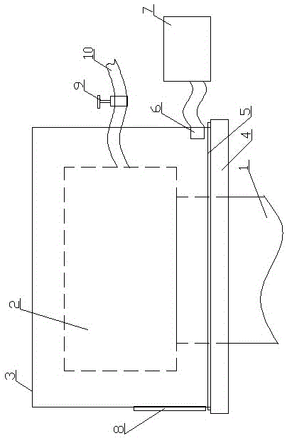
[0036] Such as figure 1 As shown, the present invention provides an insulation protection device for transformers in non-oil-filled power systems, including a pit foundation and a transformer foundation 1, the transformer 2 is arranged on the foundation 1, and the transformer is arranged on the foundation 1 A sealing plate 4, a sealing cover body 3 is movable on the sealing plate 4, a gas injection port 6 is arranged in the sealing cover body 3, and the gas injection port 6 is connected with an air drying mechanism 7. On the sealing cover body 3 The inlet and outlet 8 and the insulating oil outlet are set.
[0037] The insulating oil outlet includes an oil outlet hose 10 , and a sealing valve 9 is arranged on the oil outlet hose 10 .
[0038] The air drying mechanism 7 includes an air dryer.
[0039] The special sealing material includes raw materials and parts by weight: epoxy resin, polyvinyl chloride, polypropylene resin, phenolic resin, nylon fiber, curing agent, zeolite...
Embodiment 2
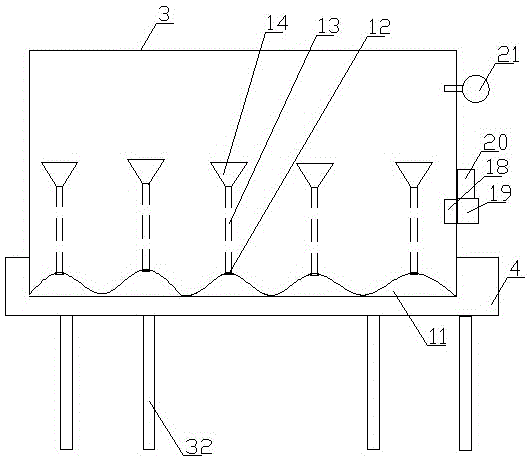
[0046] Such as figure 2 and image 3 Said: The present invention provides an insulation protection device for a transformer in an unfilled power system, including a pit foundation and a transformer foundation 1, the transformer 2 is arranged on the foundation 1, and the foundation 1 is set corresponding to the transformer A sealing plate 4, a sealing cover body 3 is movable on the sealing plate 4, a gas injection port 6 is arranged in the sealing cover body 3, and the gas injection port 6 is connected with an air drying mechanism 7. On the sealing cover body 3 The inlet and outlet 8 and the insulating oil outlet are set.
[0047] The edge of the sealing plate 4 is connected to the sealing cover 3 through a sealing mechanism 5, and the sealing mechanism 5 adopts a liquid metal seal.
[0048] The sealing mechanism 5 includes a groove body 11 corresponding to the sealing cover body 3. The lower end of the sealing cover body 3 is wave-shaped, and a liquid metal injection hole 1...
Embodiment 3
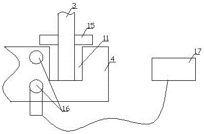
[0058] Such as figure 2 , Figure 4 As shown, the present invention provides an insulation protection device for transformers in non-oil-filled power systems, including a pit foundation and a transformer foundation 1, the transformer 2 is arranged on the foundation 1, and the transformer is arranged on the foundation 1 A sealing plate 4, a sealing cover body 3 is movable on the sealing plate 4, a gas injection port 6 is arranged in the sealing cover body 3, and the gas injection port 6 is connected with an air drying mechanism 7. On the sealing cover body 3 The inlet and outlet 8 and the insulating oil outlet are set.
[0059] A temperature and humidity sensor 18 is set inside the sealed cover 3 , a pressure gauge 21 is set on the sealed cover 3 , the temperature and humidity sensor 18 is connected to a controller 19 , and a display 20 is connected to the controller 19 .
[0060] The inside of the sealing cover 3 is provided with a temperature control pipeline 22, one end o...
PUM
| Property | Measurement | Unit |
|---|---|---|
| melting point | aaaaa | aaaaa |
| electrical insulator | aaaaa | aaaaa |
| strength | aaaaa | aaaaa |
Abstract
Description
Claims
Application Information
 - R&D
- Intellectual Property
- Life Sciences
- Materials
- Tech Scout
- Unparalleled Data Quality
- Higher Quality Content
- 60% Fewer Hallucinations
Browse by: Latest US Patents, China's latest patents, Technical Efficacy Thesaurus, Application Domain, Technology Topic, Popular Technical Reports.
© 2025 PatSnap. All rights reserved.Legal|Privacy policy|Modern Slavery Act Transparency Statement|Sitemap|About US| Contact US: help@patsnap.com


