
Luminous module and luminous keyboard

A technology of light-emitting modules and light-emitting units, applied in legends, electrical components, electric switches, etc., can solve the problems of light energy loss and affect the light-emitting effect of the light-emitting keyboard 1, and achieve the effect of improving the light-emitting effect

Active Publication Date: 2017-07-25
DARFON ELECTRONICS (SUZHOU) CO LTD +1
View PDF4 Cites 0 Cited by
  • Summary
  • Abstract
  • Description
  • Claims
  • Application Information

AI Technical Summary

Problems solved by technology

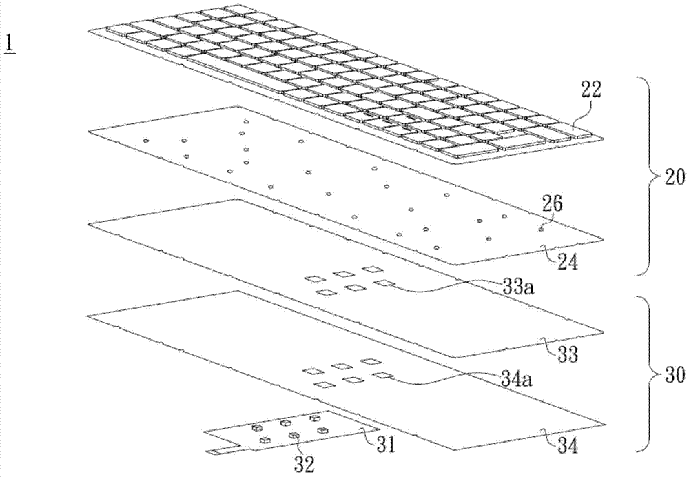
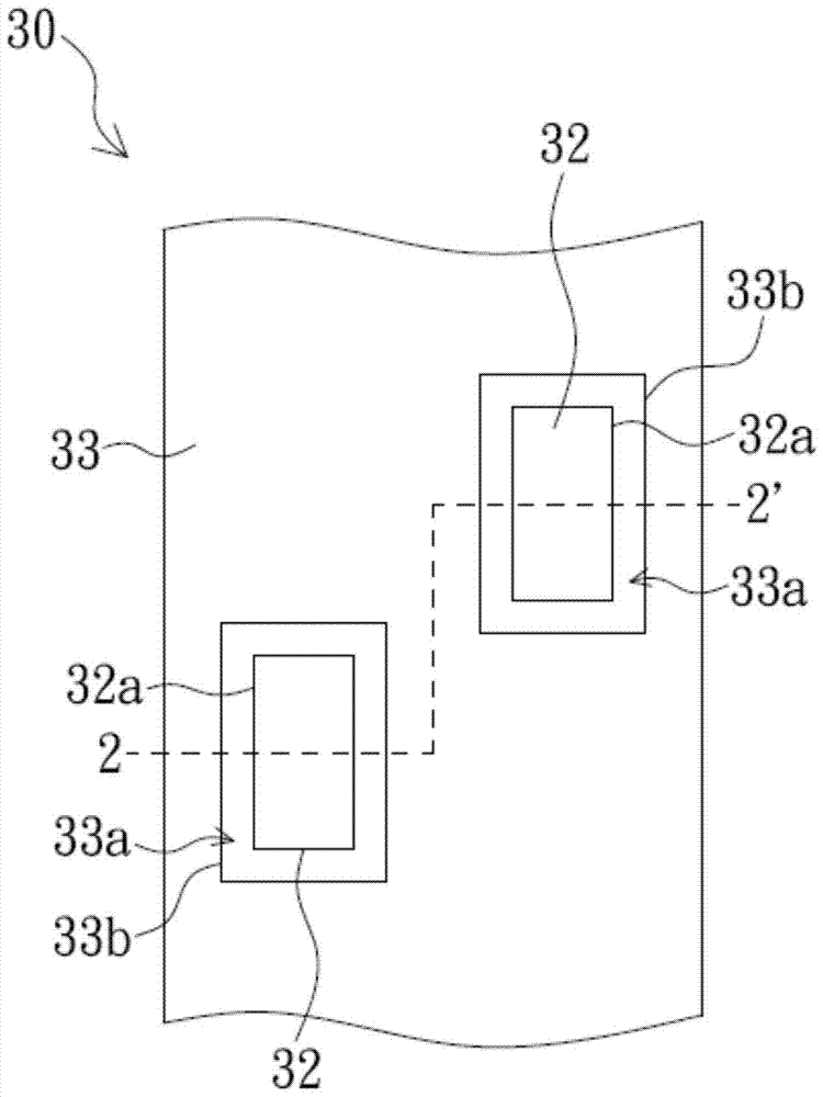
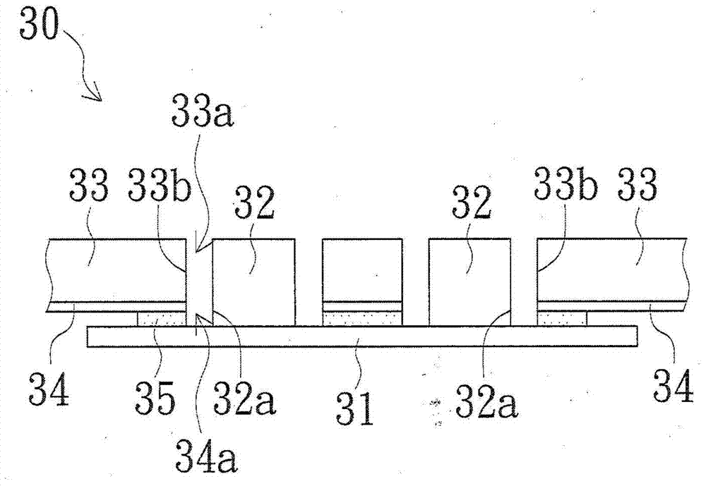
In this way, there will be a gap between the accommodating hole 33a of the light guide plate 33 and the corresponding light-emitting element 32, because of the existence of the gap, the light emitted by the light-emitting surface 32a of the light-emitting element 32 will be partially scattered in the air and transmitted to the non-metallic element. The position of the light incident surface 33b of the light guide plate 33, such as light energy loss such as scattering, causes the light intensity of the light guide plate 33 to actually receive the light emitting element 32 to be different from the light intensity emitted by the actual light emitting element 32, and further affects Overall luminous effect of luminous keyboard 1
[0004] Therefore, how to solve the problem of light energy loss caused by the gap between the light guide plate 33 and the light-emitting element 32, so as to improve the overall luminous effect of the luminous keyboard, is a technical issue that the industry needs to challenge and overcome.

Method used


Image

  • Luminous module and luminous keyboard
  • Luminous module and luminous keyboard
  • Luminous module and luminous keyboard

Examples


Embodiment Construction

[0033] Please refer to image 3 , which shows an exploded schematic diagram of a luminous keyboard according to an embodiment of the present invention. Such as image 3As shown, the light-emitting keyboard 10 of this embodiment includes a light-emitting module 100 and a key set 200, wherein the key set 200 has a plurality of keycaps 210 and a light-shielding plate 220, and the keycaps 210 can be arranged on the light-shielding plate 220, wherein the light-shielding plate 220 There are a plurality of light-transmitting holes 222 , and each keycap 210 has a light-transmitting portion (not shown in the figure), and the light-transmitting portions can respectively correspond to the light-transmitting holes 222 . Moreover, the light-emitting module 100 can emit light toward the key set 200 , that is, the light can pass through the light guide plate 140 of the light-emitting module 100 and pass through the light-transmitting hole 222 of the light-shielding plate 220 to come from ea...


PUM


Abstract

The invention relates to a light emitting module and a light emitting keyboard. The light emitting module comprises a circuit board, a light emitting unit, a transparent glue layer, a light guide plate, and a reflective layer. The light emitting unit is arranged on the circuit board, and has a light-out surface used to emit light. The transparent glue layer has a first gluing part and a second gluing part, the first gluing part has a first side and a second side which face each other, the second gluing part has a third side and a fourth side which face each other, the first side of the first gluing part is arranged on the circuit board, and the third side of the second gluing part is adhered to the light-out surface of the light emitting unit. The light guide plate has a light-in surface used to receive light transmitted via the second gluing part. The light-in surface faces the light-out surface of the light emitting unit, and the light-in surface of the light guide plate is adhered to the fourth side of the second gluing part. The reflective layer is arranged under the light guide plate, and the bottom side of the reflective layer is adhered to the second side of the first gluing part. The light-in surface of the light guide plate and the light-out surface of the light emitting unit are connected by the second gluing part, and therefore, the phenomenon of halo can be avoided.

Description

technical field [0001] The invention relates to a light-emitting module and a light-emitting keyboard, in particular to a light-emitting module and a light-emitting keyboard that can reduce the halo phenomenon generated during light-emitting. Background technique [0002] see figure 1 , which shows an exploded schematic view of a conventional luminous keyboard. Such as figure 1 As shown, the composition of the current luminous keyboard 1 may include components such as a key set 20 and a light emitting module 30 from top to bottom, wherein the key set 20 has a plurality of light-transmitting keycaps 22 and light-shielding plates 24 made of light-transmitting materials. . Generally speaking, the light emitting module 30 can have a plurality of light emitting elements 32 , and the light emitting elements 32 used as the light source of the light emitting keyboard are usually light-emitting diodes (LED, Light-Emitting Diode). The light guide plate 33 of the light-emitting mod...

Claims


Application Information

Patent Timeline
Patent Type & Authority Patents(China)
IPC IPC(8): H01H13/83
CPCH01H13/83H01H2219/056H01H2219/06
Inventor 戴宏宇杨佳运罗义童
Owner DARFON ELECTRONICS (SUZHOU) CO LTD
Learn More