Backlight module and display device

A backlight module and light source technology, which is applied in the direction of lighting devices, fixed lighting devices, lighting device components, etc., can solve the problems of reducing the effective lighting area, side-entry backlight modules are difficult to be round or irregular in shape, etc. , to achieve the effect of increasing the effective lighting area, diversifying the shape, and emitting light evenly

Active Publication Date: 2013-03-20
BOE TECH GRP CO LTD +1
View PDF5 Cites 29 Cited by
  • Summary
  • Abstract
  • Description
  • Claims
  • Application Information

AI Technical Summary

Problems solved by technology

The advantage of this side-type backlight module is that the LED as the light source enters light from the side of the light guide plate, and does not require a vertical light mixing distance, so the side-type backlight module can be ultra-thin. However, due to the light source setting On the side of the light guide plate, the light mixing distance in the horizontal direction (that is, the distance between the LED light bar 5 and the side of the light guide plate 3 ) is still required, so the outer frame of the side-type backlight module is compared to the outer frame of the direct-type backlight module. It is much larger, which relatively reduces the effective lighting area. At the same time, because the LED light bar can only be made into a straight and regular shape, it is difficult to make the side-type backlight module into a round or irregular shape.

Method used


Image

  • Backlight module and display device
  • Backlight module and display device
  • Backlight module and display device

Examples


Embodiment 1

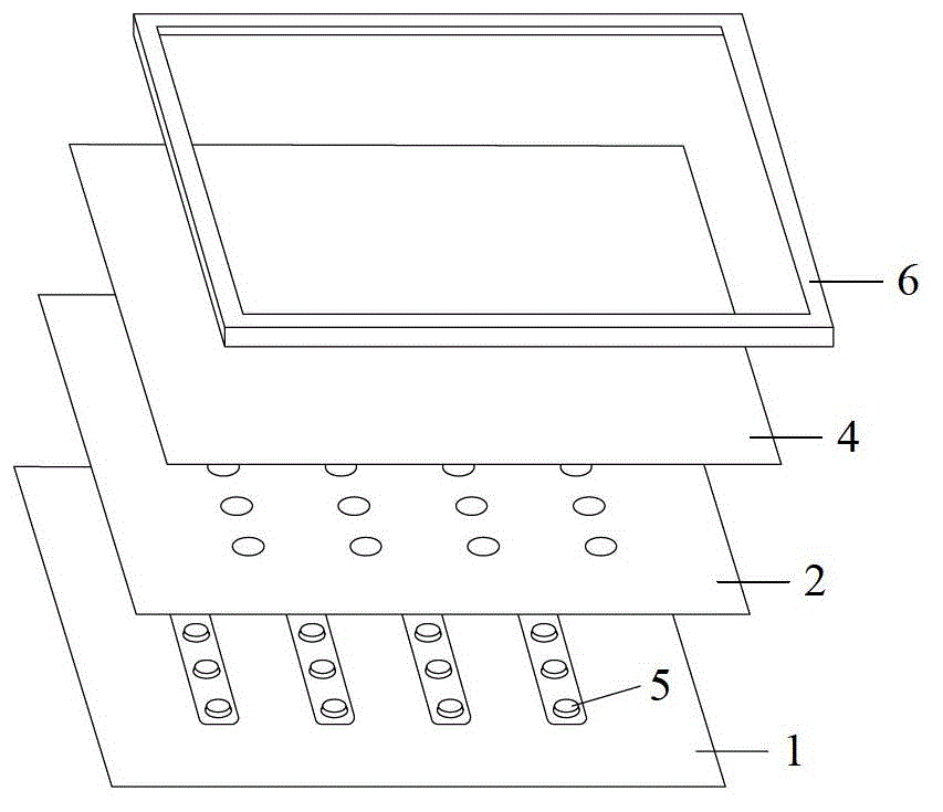
[0035] This embodiment provides a backlight module, including a light guide plate, a light source, and a reflector;

[0036] The reflective sheet includes a first reflective sheet and a second reflective sheet.

[0037] The first reflective sheet is arranged on the side of the light guide plate, the second reflective sheet is arranged on the bottom of the light guide plate, the light source is arranged below the first reflective sheet, and the first reflective sheet It is used to reflect the light emitted by the light source to the inside of the light guide plate, and the light is emitted from the top of the light guide plate after being scattered by the light guide plate and reflected by the second reflection sheet.

[0038] This embodiment also provides a display device including the above-mentioned backlight module.

[0039] It can be seen that the light emitted by the light source in the backlight module described in this embodiment is reflected by the first reflection sh...

Embodiment 2

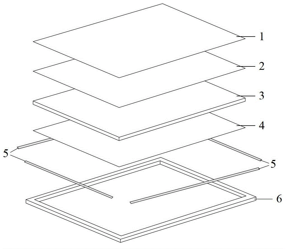
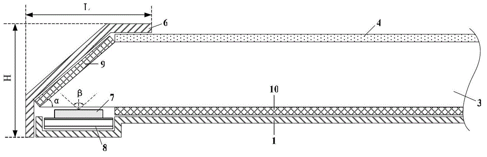
[0041] like image 3 As shown, this embodiment provides a backlight module, including a light guide plate 3, a light source 7, a PCB board (printed circuit board) 8, an optical film material 4, a first reflection sheet 9, a second reflection sheet 10, a backplane 1 and the outer frame 6. The optical film material 4 includes a diffuser.

[0042] Wherein, the first reflection sheet 9 is arranged on the side of the light guide plate 3, specifically, it can be arranged on any one or more sides of all the sides of the light guide plate, and of course it can also be arranged on all sides around the light guide plate; The second reflection sheet 10 is arranged at the bottom of the light guide plate 3; the light source 7 is arranged below the first reflection sheet 9 and on the PCB board 8. It should be noted that the light source 7 is also arranged below the light guide plate 3, and in order to prevent the light source 7 from heating and causing the light guide plate 3 to be heated...

Embodiment 3

[0055] like Figure 4 As shown, the difference between the backlight module described in this embodiment and Embodiment 3 is:

[0056] The light guide plate 3 in the backlight module also includes a protrusion 3a disposed on its bottom edge, the protrusion 3a extends into the concave portion of the back plate 1, and the light source 7 is disposed on the protrusion 3a (the light source 7 is not in contact with the protrusion 3a), so as to avoid that the light emitted from the part of the light source close to the first reflector 9 cannot be transmitted to the optical film material 4 due to the limitation of the light emitting angle of the light source As a result, the resulting light loss improves the utilization rate of the reflected light after the light emitted by the light source is reflected by the first reflective sheet 9 .

[0057] Preferably, the relationship between the thickness B of the protrusion 3a, the width D of the protrusion 3a, and the light emitting angle β ...


PUM

PropertyMeasurementUnit
thicknessaaaaaaaaaa

Abstract

The invention provides a backlight module which comprises a light source, a light guide plate and reflective sheets, wherein the reflective sheets comprise a first reflective sheet and a second reflective sheet; the first reflective sheet is arranged on the lateral surface of the light guide plate; the second reflective sheet is arranged at the bottom of the light guide plate; the light source is arranged below the first reflective sheet; the first reflective sheet is used for reflecting light emitted by the light source into the light guide plate; and after being scattered by the light guide plate and reflected by the second reflective sheet, the light is emitted out from the top of the light guide plate. Correspondingly, the invention provides a display device which comprises the backlight module. The backlight module provided by the invention has the advantages of thinning, increase of an effective lighting area, shape diversification and the like.

Description

technical field [0001] The invention relates to the technical field of display manufacturing, in particular to a backlight module and a display device including the backlight module. Background technique [0002] Liquid crystal displays have occupied a dominant position in the current flat panel display market due to their small size, low power consumption, and low radiation. In the liquid crystal display, since the liquid crystal itself does not emit light, it only regulates the light. In order to display images on the screen of the liquid crystal display, it is necessary to configure a backlight module (BLU, Back Light Unit) for the display panel (Panel). [0003] Generally speaking, the backlight module can be divided into side-type backlight module and direct-type backlight module according to the position of the light source in the backlight module, wherein the light source in the side-type backlight module is located on the side of the display panel. , the light sourc...

Claims


Application Information

Patent Timeline
Patent Type & Authority Applications(China)
IPC IPC(8): F21S8/00F21V13/04G02F1/13357
CPCG02B6/0031G02B6/009G02B6/0055G02B6/0051
Inventor 赵扬周振东
Owner BOE TECH GRP CO LTD
Why Eureka
Try Eureka