Display device assembly and manufacture thereof

Active Publication Date: 2014-08-05
E INK CALIFORNIA
View PDF88 Cites 34 Cited by
  • Summary
  • Abstract
  • Description
  • Claims
  • Application Information

AI Technical Summary

Benefits of technology

[0022]Without a substrate layer between a display device and a luminance enhancement struc

Problems solved by technology

The lack of satisfactory brightness is often a concern for electrophoretic display devices.
This total internal reflection phenomenon may result in a loss of about 30-50% of the scattering light, thus causing reduction in brightness of the display device.
Unfortunately, the performance of such a luminance enhancement struc

Method used


Image

  • Display device assembly and manufacture thereof
  • Display device assembly and manufacture thereof
  • Display device assembly and manufacture thereof

Examples


Embodiment Construction

I. Conventional Display Devices

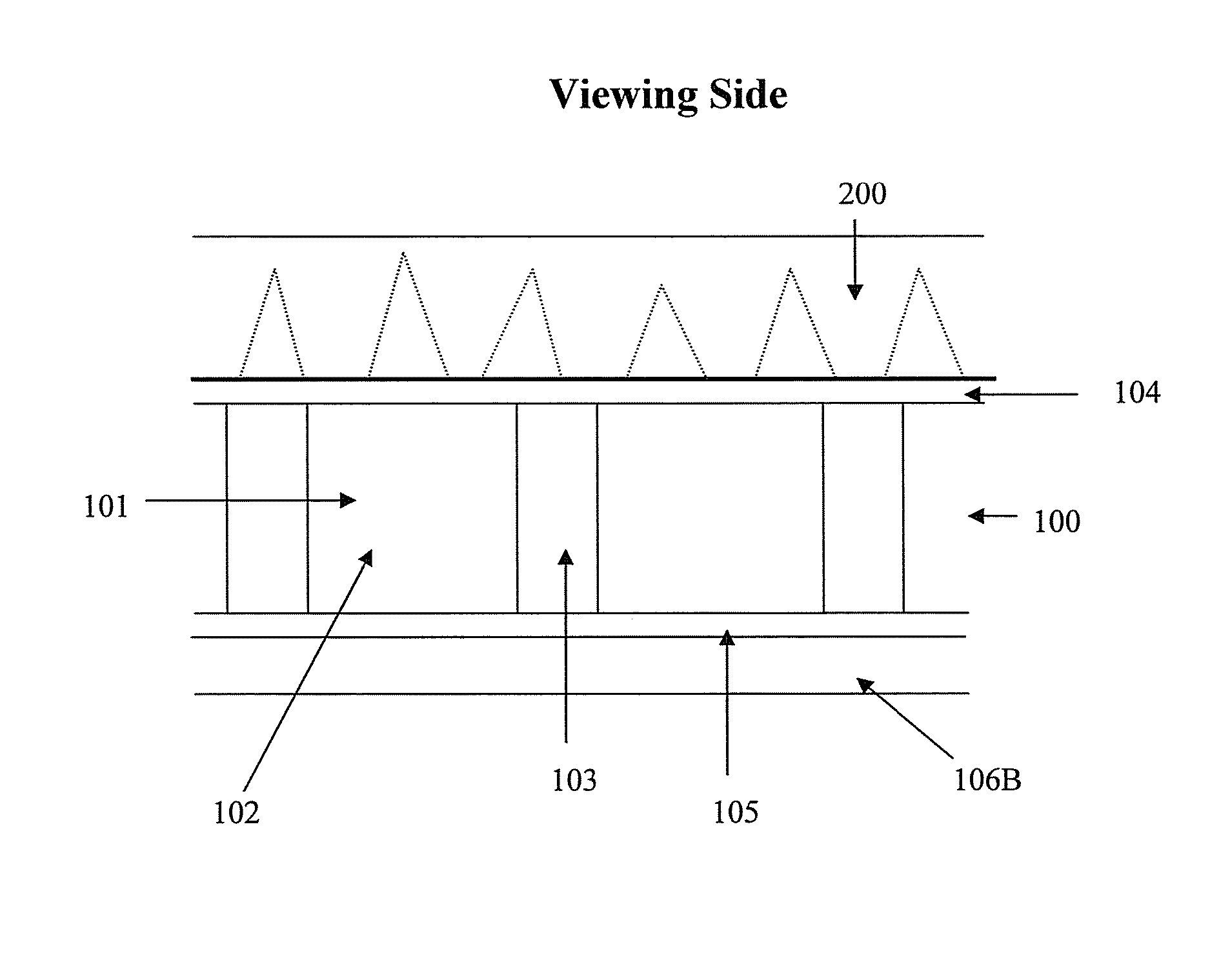
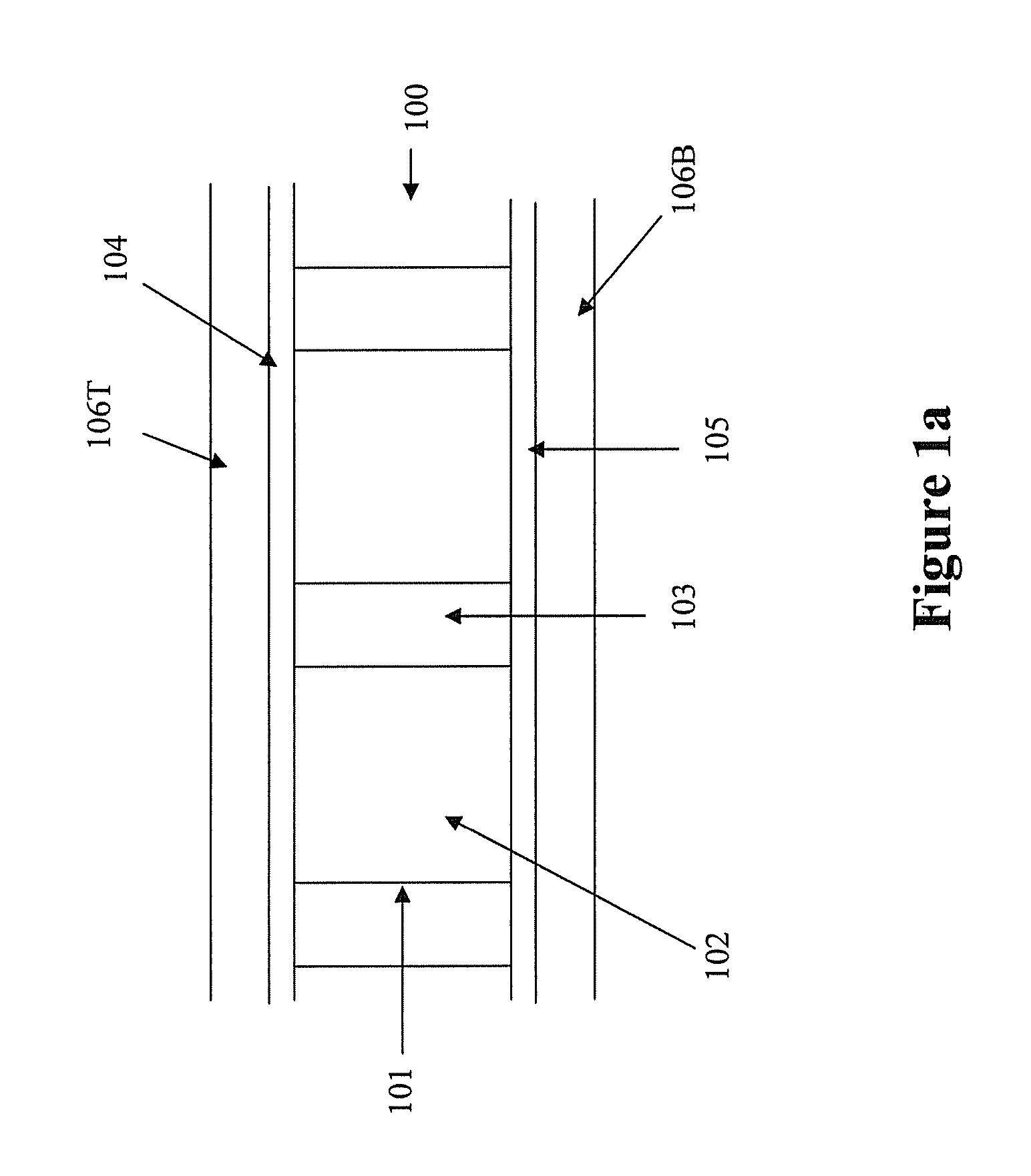
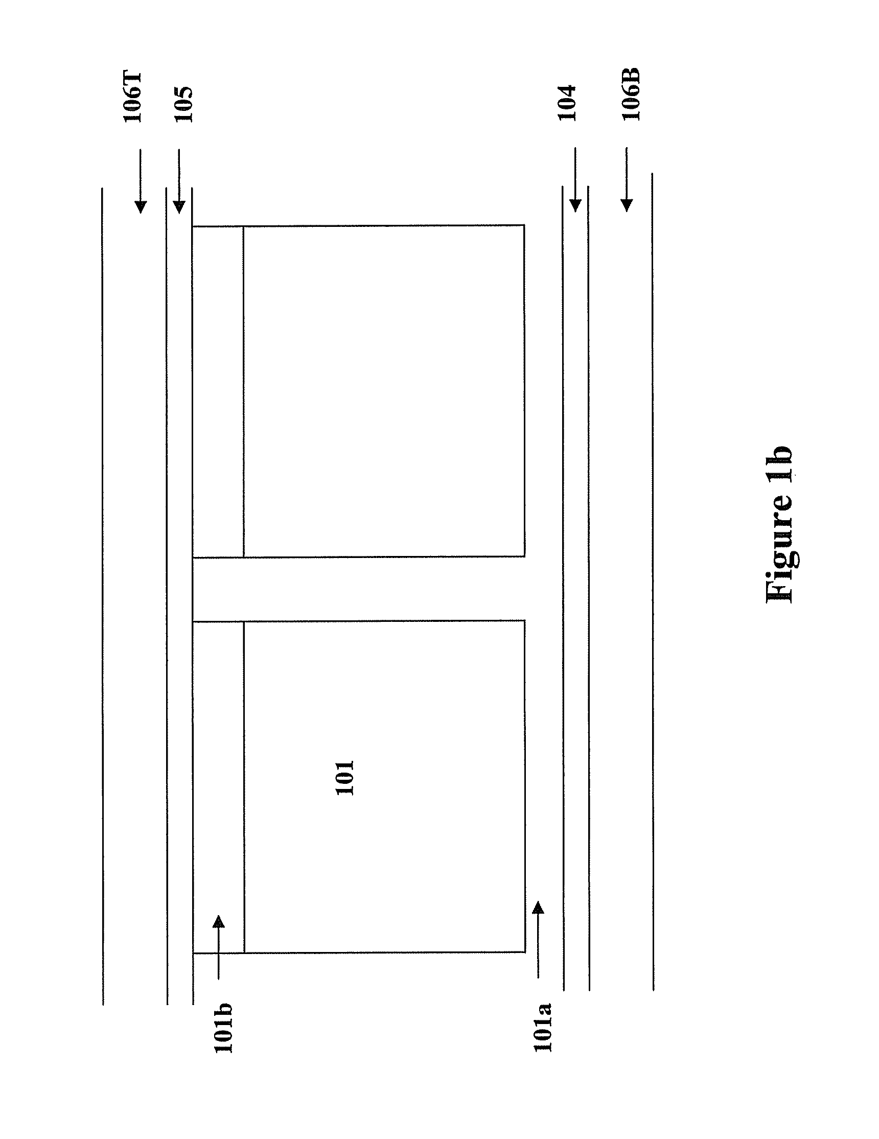
[0030]FIG. 1a illustrates a display device (100). The device comprises display cells (101) which are filled with a display fluid (102) and sandwiched between two electrode layers (104 and 105). Each of the display cells is surrounded by partition walls (103).

[0031]For an electrophoretic display, the display cells are filled with an electrophoretic fluid which comprises charged pigment particles dispersed in a solvent. The display fluid may be a system comprising one or two types of particles.

[0032]In the system comprising only one type of particles, the charged pigment particles are dispersed in a solvent of a contrasting color. The charged particles will be drawn to one of the electrode layers (104 or 105), depending on the potential difference of the two electrode layers, thus causing the display panel to show either the color of the particles or the color of the solvent, on the viewing side.

[0033]In a system comprising particles carrying opposite ch...


PUM


Abstract

The present invention is directed to a display device assembly which comprises a display device and a luminance enhancement structure. The luminance enhancement structure is directly laminated onto an ITO layer with an adhesive. The assembly of the present invention provides improved performance of the luminance enhancement structure.

Description

[0001]This application claims priority to U.S. Provisional Application No. 61 / 228,074, filed Jul. 23, 2009; the content of which is incorporated herein by reference in its entirety.FIELD OF THE INVENTION[0002]The present invention is directed to a display device assembly which comprises a display device and a luminance enhancement structure, and processes for its manufacture.BACKGROUND OF THE INVENTION[0003]The lack of satisfactory brightness is often a concern for electrophoretic display devices. Total internal reflection inevitably would occur with an electrophoretic display device because such a display device usually has components of a high refractive index. Due to the components having a higher refractive index (e.g., about 1.5) than the air (which has a refractive index of about 1) surrounding the device, some of the scattering light from the display panel may reflect off the display front surface and back to the display device by total internal reflection. This total interna...

Claims


Application Information

Patent Timeline
IPC IPC(8): G02B26/00
CPCG02B26/00G02B5/0284G02B5/0231G02B5/0278G02B6/0053G02F1/133504G02F2001/133507G02F2001/133562G02F2001/1672G02F1/1681G02F1/133507G02F1/133562
Inventor SPRAGUE, ROBERT A.CHAN, BRYAN HANSLIN, CRAIG
Owner E INK CALIFORNIA
Why Eureka
Try Eureka