Touch control type organic light-emitting display panel

A light-emitting display, touch-sensitive technology, applied in organic semiconductor devices, semiconductor devices, electrical components, etc., can solve the problems of corrosion of organic functional layers and motor materials, affecting device life, blue light intensity, etc., to enhance performance and improve color. Purity, good eye protection effect

Active Publication Date: 2015-12-02
EVERDISPLAY OPTRONICS (SHANGHAI) CO LTD
View PDF3 Cites 4 Cited by
  • Summary
  • Abstract
  • Description
  • Claims
  • Application Information

AI Technical Summary

Problems solved by technology

However, the visible light emitted by the current touch organic light-emitting display panels contains blue light (below 438nm) which is harmful to human eyes, and the blue light is strong; in addition, because OLED devices are very sensitive to water vapor and oxygen, once water vapor and Oxygen infiltration will corrode the organic functional layer and motor materials, etc., seriously affecting the life of the device

Method used


Image

  • Touch control type organic light-emitting display panel
  • Touch control type organic light-emitting display panel
  • Touch control type organic light-emitting display panel

Examples


Embodiment 1

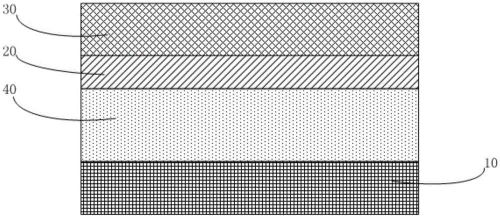
[0023] see figure 1 , is a schematic diagram of a touch-sensitive organic light-emitting display panel according to Embodiment 1 of the present invention, which includes an organic light-emitting diode device 10 , a polarizer 20 stacked on the light-emitting surface of the organic light-emitting diode device 10 , and a polarizer positioned between the polarizers 20 The touch panel 30 on the top; wherein, a dielectric layer 40 is provided between the polarizer 20 and the organic light emitting diode device 10 .

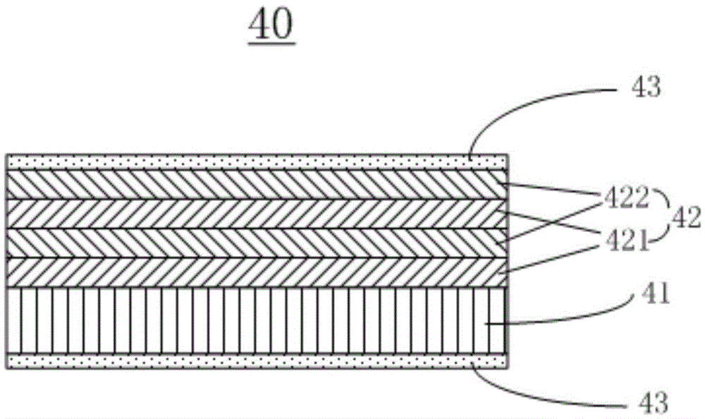
[0024] see figure 2 , the dielectric layer 40 includes a film substrate 41 and a Bragg reflector layer 42 formed on the film substrate.

[0025] The Bragg reflector layer 42 includes a first layer and a second layer alternately stacked along its thickness direction, the refractive index of the second layer is at least 0.5 higher than that of the first layer, and the one closest to the film substrate 41 is the second layer. layer. The Bragg reflector layer 42 has n ...

Embodiment 2

[0036] like image 3 As mentioned above, the schematic diagram of the touch-sensitive organic light emitting display panel of the second embodiment.

[0037] The difference from Embodiment 1 is that the dielectric layer 40 is located between the polarizer 20 and the touch panel 30 .

[0038] Others are the same as in Embodiment 1, and will not be repeated here.

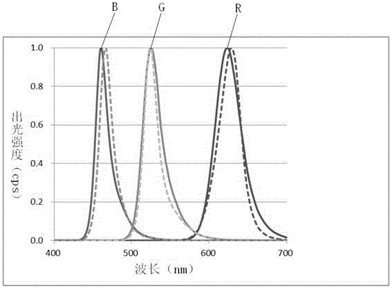
[0039]In the touch-sensitive organic light-emitting display panel of the present invention, the inventors have found through a lot of research that a specific Bragg The dielectric layer 40 of the reflector layer structure, on the one hand, can greatly reduce the blue light below 438nm that is harmful to human eyes, thereby achieving the purpose of eye protection; secondly, the inventor unexpectedly found that the Bragg The structure of the reflector layer 42 can not only play the role of controlling the microcavity, but also form a resonant cavity effect corresponding to the organic optical microcavity in the organi...


PUM


Abstract

The invention relates to a touch control type organic light-emitting display panel. A dielectric layer with a specific Bragg reflector layer structure is disposed between a polaroid and an organic light-emitting diode device or between the polaroid and a touch control panel. In this way, 438nm blue light that is harmful to the eyes of people can be greatly reduced, and an eye protection purpose is achieved. Meanwhile, the inventor accidentally finds that the Bragg reflector layer structure plays a micro-cavity control effect, and can correspond to an organic optical micro-cavity in the device to form a resonator effect, so the spectrum of the display panel is controlled, and the purity is improved. Moreover, in terms of the outer dielectric layer attached to the device, different Bragg reflector layer structures can be designed on the basis of different devices and different demands, and thus a better eye protection effect is achieved. Furthermore, the Bragg reflector layer of the dielectric layer helps to improve the performance of water-resisting oxygen and improve the packaging effect.

Description

technical field [0001] The present invention relates to an organic light emitting display panel, in particular to a touch organic light emitting display panel. Background technique [0002] OLED (Organic Light-Emitting Diode, Organic Light-Emitting Diode) display technology has the characteristics of self-illumination. It uses very thin organic material coating and glass substrate. When current passes through, these organic materials will emit light, and the viewing angle of OLED display screen Large, and can significantly save power. Since the OLED display technology has many incomparable advantages over the LED (Light-Emitting Diode, light-emitting diode) display technology, the OLED display technology has been widely used in the display field. [0003] For example, an OLED display panel can also be combined with a touch panel to form a touch display panel. However, the visible light emitted by the current touch organic light-emitting display panels contains blue light (...

Claims


Application Information

Patent Timeline
Patent Type & Authority Applications(China)
IPC IPC(8): H01L27/32
CPCH10K59/40H10K77/111H10K50/852H10K50/844H10K2102/311H10K59/12
Inventor 张明月杨正杰邹忠哲施秉彝
Owner EVERDISPLAY OPTRONICS (SHANGHAI) CO LTD
Why Eureka
Try Eureka