Plant facilities management system and plant facilities management system control method

A technology for management systems and factory equipment, applied in general control systems, control/adjustment systems, test/monitoring control systems, etc., can solve problems such as missing abnormal omens, and achieve the effect of effective analysis

Active Publication Date: 2015-12-02
HITACHI LTD
View PDF10 Cites 12 Cited by
  • Summary
  • Abstract
  • Description
  • Claims
  • Application Information

AI Technical Summary

Problems solved by technology

The possibility of finding abnormal signs depends on the proficiency of managers, etc. Unskilled managers may miss abnormal signs

Method used


Image

  • Plant facilities management system and plant facilities management system control method
  • Plant facilities management system and plant facilities management system control method
  • Plant facilities management system and plant facilities management system control method

Examples


Embodiment 1

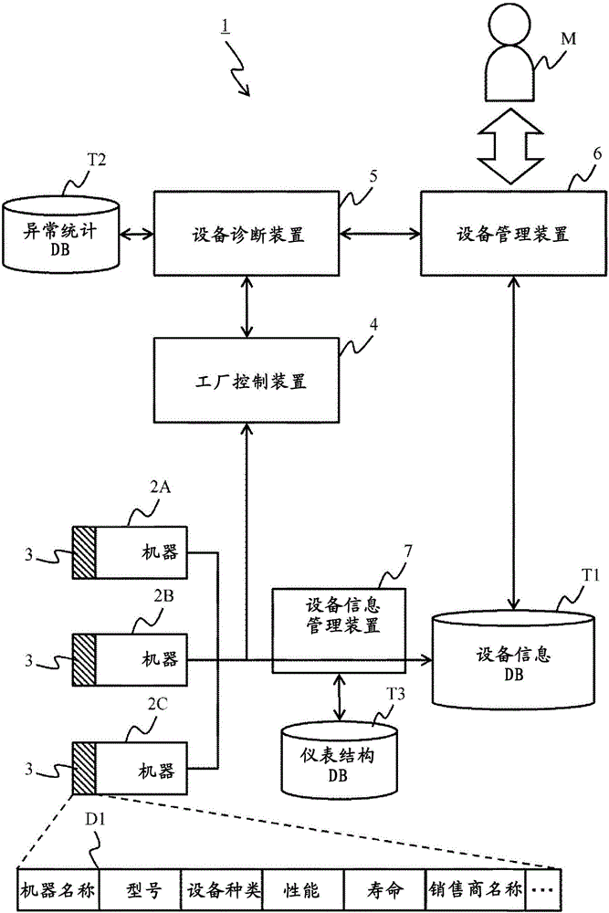
[0029] figure 1 The overall structure of the plant equipment management system 1 is shown. For example, a plurality of devices 2A to 2C are installed in factories such as power plants and chemical plants. When there is no need to distinguish the respective machines 2A to 2C, they are referred to as machine 2 .

[0030] Each machine 2 is, for example, a sensor, an actuator, a controller, etc., specifically corresponding to a temperature sensor, a pressure sensor, a flow sensor, a viscosity sensor, a distance sensor, a quality sensor, a color sensor, an illumination sensor, a gas sensor, a solenoid valve, a pneumatic Regulating valves, solenoids, heaters, refrigerators, motors, generators, transformers, turbines, boilers, pumps, compressors, mixers, fans, filters, sequencers, control panels, regulators, recorders, etc. That is, each device 2 includes both main equipment and incidental equipment.

[0031] Each device 2 includes a device information storage unit 3 for storing d...

Embodiment 2

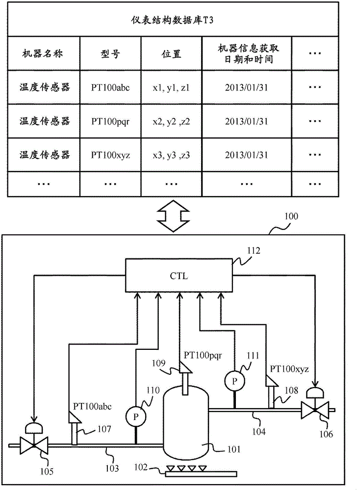
[0073] use Figure 6 and Figure 7 A second embodiment will be described. This embodiment corresponds to a modified example of the first embodiment, so the description will focus on differences from the first embodiment. In the present embodiment, the device to be replaced is specified on the device configuration diagram 100, and the device information database T1 is updated with device information from the newly installed device.

[0074] Figure 6 It is an explanatory diagram showing the instrument configuration database T3 and the instrument configuration diagram 100 . The devices 2 in the factory are appropriately replaced in order to cope with aging or to improve measurement accuracy, for example.

[0075] The manager designates the device to be replaced (here, the tank temperature sensor 109 ) on the instrument configuration diagram 100 . In order to distinguish the designated replacement device from other devices, the display method may be changed by blinking or th...


PUM


Abstract

The purpose of the present invention is to efficiently manage plant facilities. Equipment (2) in a plant is maintained so that equipment information (D1) related to the equipment can be read. A facility information management device (7) generates facility information by acquiring equipment information from each piece of equipment, and stores the facility information to a facility information database (T1). A facility diagnosis device (5) acquires operation data relating to each piece of equipment from a plant control unit that controls a plurality of pieces of equipment, and detects whether there is prescribed change on the basis of the difference between the operation data and statistical data recorded to an abnormality statistics database (T2). If the existence of a prescribed change is detected, a facility management device (6) associates and analyzes the operation data and facility information, and presents the analysis results to a manager (M).

Description

technical field [0001] The invention relates to a factory equipment management system and a control method of the factory equipment management system. Background technique [0002] For example, factories such as power plants and chemical plants have a large number of various types of equipment, and it is necessary to manage these equipment (equipment management). Therefore, the manager manually registers the information on the machines used in various parts of the factory in the database one by one, and adds information obtained through periodic inspections and the like to the database. Thereby, it is possible to manage the static state of the factory equipment for a certain period of time. [0003] On the other hand, large and small abnormal states such as machine failure, signal line disconnection, piping leakage, and aging of the actuator are discovered through patrol inspections by operators or managers, and maintenance operations are performed. The possibility of disc...

Claims


Application Information

Patent Timeline
Patent Type & Authority Applications(China)
IPC IPC(8): G05B23/02
CPCG05B23/024
Inventor 北川胜秀朝仓一安深井雅之丸山良雄清水悟村上正博
Owner HITACHI LTD
Why Eureka
Try Eureka