Sedimentation tank that can be cleaned automatically for road and bridge construction

An automatic cleaning and sedimentation tank technology, applied in the sedimentation tank and other directions, can solve the problems of unsatisfactory cleaning effect, environmental pollution, oil consumption and other problems, and achieve the effects of low construction cost, flexibility and fast operation speed.

Active Publication Date: 2017-01-25
NO 3 ENG LIMITED OF CR20G
View PDF4 Cites 0 Cited by
  • Summary
  • Abstract
  • Description
  • Claims
  • Application Information

AI Technical Summary

Problems solved by technology

The current sedimentation tanks are basically dug on the construction site to surround the pits. When cleaning, use loaders or excavators to dig out the sediment waste from the sedimentation tanks. Cleaning with excavators consumes a lot of fuel and the cleaning effect is not good. Ideally, manual secondary cleaning is required after each mechanical cleaning, and the excavator is likely to collide with the side wall of the sedimentation tank during operation, causing water leakage. Since the sedimentation water in the sedimentation tank contains chemical additives, once it leaks, it will cause water leakage. Serious environmental pollution affects normal construction

Method used


Image

  • Sedimentation tank that can be cleaned automatically for road and bridge construction
  • Sedimentation tank that can be cleaned automatically for road and bridge construction
  • Sedimentation tank that can be cleaned automatically for road and bridge construction

Examples


Embodiment Construction

[0010] The specific embodiments of the present invention are as follows:

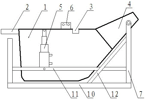
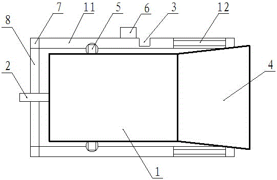
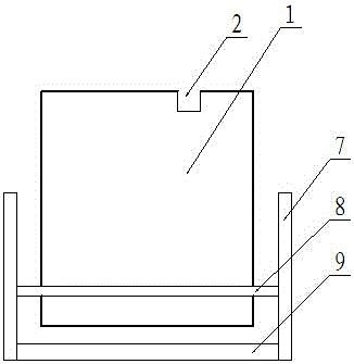
[0011] Fix two longitudinal beams (10) between the ends of the two transverse beams (8), respectively fix the upright column (7) on each corner connecting the transverse beam (8) and the longitudinal beam (10), 7) At the upper end, a horizontal connecting beam (9) and a longitudinal connecting beam (11) are used to connect the vertical column (7) vertically and horizontally to form a box. A sedimentation tank (1) is set between the boxes. A sewage tank (3) is arranged on the side, a drainage groove (2) is arranged at one end of the longitudinal direction of the sedimentation tank (1), and a drainage groove (4) is arranged at the other end. The two sides of the drainage groove (4) are respectively connected to the vertical column (7). ) Hinge connection, using diagonal bracing (12) to connect the column (7), the longitudinal beam (10) and the longitudinal connecting beam (11) to each other, between the two ...


PUM


Abstract

The invention provides a sedimentation tank capable of being automatically cleaned for road and bridge construction. According to the sedimentation tank, longitudinal beams are fixed between two transverse beams, stand columns are fixed on all connected corners of the longitudinal beams and the transverse beams, the stand columns are connected longitudinally and transversely through transverse connecting beams and longitudinal connecting beams at the upper ends of the stand columns to form a box body, the sedimentation tank is arranged in the box body, one side of the sedimentation tank is provided with a sewage tank, one longitudinal end of the sedimentation tank is provided with a water draining tank, the other longitudinal end of the sedimentation tank is provided with an object discharging tank, the two sides of the object discharging tank are hinged to the stand columns, and lifting oil cylinders are connected between the two sides of the sedimentation tank and the longitudinal connecting beams in a hinged mode respectively. According to the sedimentation tank, the defects existing in a current sedimentation tank cleaning device for road and bridge construction are overcome, the operation speed is high, the energy consumption is low, energy conservation and environment protection are achieved, no pollution exists, operation is easy, cleaning is convenient and fast, mechanic operation is flexible, the construction cost is low, the working efficiency is high, the sediment waste can be independently removed without needing assistance of a loader or an excavator, and the sedimentation tank can be widely applied to construction sites, provided with the sedimentation tank, in the fields of road and bridge construction, building construction and the like.

Description

Technical field [0001] The invention relates to a sedimentation tank cleaning device for road and bridge construction, in particular to a sedimentation tank that can be automatically cleaned in road and bridge construction, and belongs to the field of road and bridge construction. Background technique [0002] With the rapid development of national economic construction, road and bridge construction has entered an unprecedented stage of development. While the country requires high standards for road and bridge construction quality, it also requires strengthening the concept of energy saving, environmental protection, and green and low-carbon construction. In order to improve the construction environment, reduce The labor intensity of the construction personnel and the improvement of construction quality. According to the requirements of construction technical specifications, sedimentation tanks must be set up at the concrete mixing station, construction tunnel exit, and other cons...

Claims


Application Information

Patent Timeline
Patent Type & Authority Patents(China)
IPC IPC(8): B01D21/02
Inventor 马小利张骅张奇马威锁福荣黄炬银宋小军杨启维赵勇魏碧辉
Owner NO 3 ENG LIMITED OF CR20G
Why Eureka
Try Eureka