Machine and method for installing dry battery electric torch front conductive bridge

A conductive bridge and flashlight technology, which is applied to the parts of lighting devices, lighting devices, lighting and heating equipment, etc., can solve the problems of large impact on production efficiency, high labor intensity, scratches on iron bridge feet, etc., to improve production efficiency , Reduce work intensity, improve the effect of enterprise production efficiency

Active Publication Date: 2015-12-09
GUANGDONG JINYUAN LIGHTING TECH
View PDF5 Cites 0 Cited by
  • Summary
  • Abstract
  • Description
  • Claims
  • Application Information

AI Technical Summary

Problems solved by technology

[0003] Although the traditional installation method of the front conductive bridge can meet the basic needs, there are still the following problems: 1. During installation and production, the fingers of the workers often scratch the feet of the iron bridge, which is poor

Method used


Image

  • Machine and method for installing dry battery electric torch front conductive bridge
  • Machine and method for installing dry battery electric torch front conductive bridge
  • Machine and method for installing dry battery electric torch front conductive bridge

Examples


Embodiment Construction

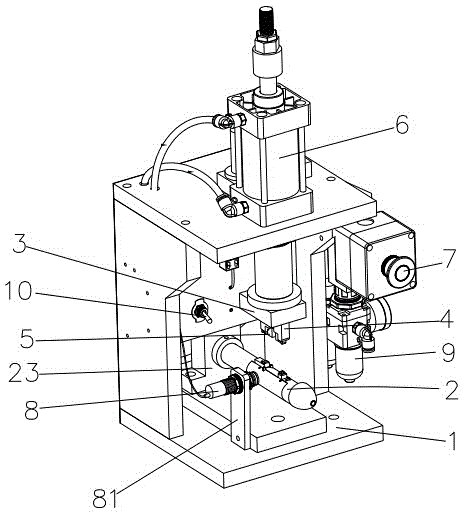
[0025] Such as Figure 3-8 As shown, a conductive bridge installation machine before a dry battery flashlight of the present invention includes a body 1, a positioning support rod 2, an installation base 3, a foot folding mold 4, a compression mold 5, a cylinder 6 and a start switch 7.

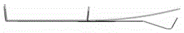
[0026] Wherein, the above-mentioned positioning support bar 2 includes a cross bar 21 and a positioning slider 22 installed in the cross bar and capable of moving up and down. One end of the cross bar 21 is fixed on the middle part of the body through the installation seat plate 23, and the other end is suspended in the air. The positioning slider 22 includes two positioning bosses, a connecting plate 221 connecting the bottom ends of the two positioning bosses, mounting ears 222 mounted on the positioning bosses and two positioning washers 223 . The two positioning protrusions are respectively a front positioning protrusion 224 close to the free end of the cross bar 21 and a rear positioning...


PUM


Abstract

The invention discloses a machine for installing a dry battery electric torch front conductive bridge. The machine comprises a machine body, a positioning supporting rod, an installation base, a bent foot mold with bent feet, a compression mold with compression feet, an air cylinder and a start switch. The positioning supporting rod comprises a transverse rod and a positioning sliding block, wherein the positioning sliding block is installed in the transverse rod and can move up and down. The positioning sliding block is provided with two positioning protruding columns corresponding to the two bent feet of the bent foot mold. One end of the transverse rod is fixed in the middle of the machine body through an installation base plate, and the other end of the transverse rod is suspended. The air cylinder is fixedly installed on the upper portion of the machine body. The bent foot mold and the compression mold are installed on a piston rod of the air cylinder through the installation base. According to the machine, the structure is simple, the front conductive bridge can be automatically bent and compressed at a time, production efficiency is effectively improved, and operation stability of workers is improved. In addition, the mode of directly bending and compressing iron bridge feet by hand is changed, the working intensity of the workers is relieved, and the problem that the fingers of the workers are frequently scratched by the iron bridge feet is solved.

Description

technical field [0001] The invention relates to the technical field of flashlight production equipment, in particular to a dry battery flashlight front conductive bridge installation machine and a front conductive bridge installation method. Background technique [0002] Today, with the rapid development of science and technology, it is the necessity and trend of social development that automated production replaces manual production. At present, the production of dry cell flashlights has been in a state of pure manual production for a long time. In the installation process of the front conductive bridge of the flashlight, the existing installation method is to first manually combine the front conductive bridge and the rubber bridge (such as figure 1 shown) into the barrel mounting hole (eg figure 2 shown), and then the workers will manually break the iron bridge feet, fix the iron bridge on the cylinder body, and finally use a manual punch to press the iron bridge feet t...

Claims


Application Information

Patent Timeline
IPC IPC(8): B23P19/04F21V17/16
CPCB23P19/04F21V17/164
Inventor 李立群陈育郑雄文谢礼潮
Owner GUANGDONG JINYUAN LIGHTING TECH
Why Eureka
Try Eureka