A fuel engine and electric motor linkage separation system

A fuel engine and separation system technology, which is applied to the layout of multiple prime movers, power devices, and air pressure power devices of general power devices, can solve problems such as damage, uneven power transmission, and burst transmission structures, and achieve The effect of safe and durable use, increased force bearing area, and reliable transmission

Active Publication Date: 2019-01-15
冯德洲
View PDF6 Cites 0 Cited by
  • Summary
  • Abstract
  • Description
  • Claims
  • Application Information

AI Technical Summary

Problems solved by technology

The linkage clutch mechanism commonly used in the prior art is a ball type one-way clutch (such as figure 1 shown) and roller clutches (as figure 2 As shown), it is characterized in that the driving disc and driven disc of the clutch mechanism can be engaged or separated through balls or rollers, so as to realize the linkage or separation of the fuel engine and the output shaft of the electric motor. The balls or rollers of this type of clutch and the active The contact between the disc and the driven disc is point-like contact. Because the contact surface is too small, it cannot adapt to the transmission of large torque, and it is easy to cause serious wear of the balls or rollers, uneven power transmission, and easy damage; especially for roller clutches. Not only the structure and size are large, but also it cannot adapt to the transmission of large torque. After a period of use, the rollers will be slightly worn, or due to dust and oil, they will lose their transmission effect; the ball clutch is relatively small in size, but the structure cannot adapt to large torque. Torque transmission, it is easy to cause serious wear or direct damage to the balls in the case of sudden torque. In severe cases, it will burst or the transmission structure will be stuck, resulting in power failure of the transmission system. The above two clutch structures are under high torque transmission. Obvious defects, high maintenance costs, not even suitable for use

Method used


Image

  • A fuel engine and electric motor linkage separation system
  • A fuel engine and electric motor linkage separation system
  • A fuel engine and electric motor linkage separation system

Examples


Embodiment 1

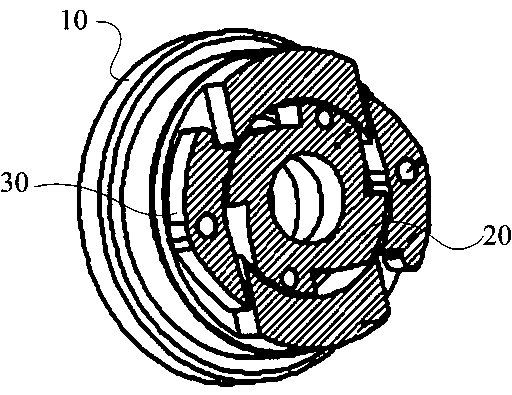
[0023] refer to image 3 The schematic diagram of the structure is shown.

[0024] A fuel engine and electric motor linkage separation system according to an embodiment of the present invention includes a driving disc 10 and a driven disc 20 of a clutch mechanism, the driving disc 10 is connected to the fuel engine power output shaft, and the power of the driven disc and the motor The output shaft 11 is connected, and the power output shaft 11 of the electric motor is also the power output shaft of the clutch mechanism.

[0025] The end face of the driving disc 10 has an inner cavity, the driven disc 20 is rotatably arranged in the inner cavity, the inner cavity wall of the driving disc 10 is provided with a notch groove for accommodating the clutch block 30, and the clutch block 30 is rotatably arranged in the notch groove Inside.

[0026] And there are at least two clutch blocks, which are symmetrically distributed on the inner cavity wall of the driving disc 10, preferabl...

Embodiment 2

[0035] refer to Figure 9 The schematic diagram of the structure is shown.

[0036] In this embodiment, the driving disc 10 is rotatably disposed in the inner cavity of the driven disc 20, and the clutch block 30 is rotatably disposed on the end surface of the driving disc 10. There are at least two clutch blocks 30, which are symmetrically distributed on the driving disc 10. On the wall of the lumen, preferably two pieces in this embodiment.

[0037] The inner cavity wall of the driven disc 20 is recessed to form a ratchet pawl 21, and a matching convex surface 33 is set on the outer wall of the clutch block 30. When the driving disc 10 is running, the clutch block is under the action of centrifugal force. The concave ratchet pawl 21 card contact connection of the disc 20, such as Figure 10 The schematic diagram of the structure is shown.

[0038] In order to further reduce the frictional force, convex arc points 34 are provided on the surface of the clutch block and the ...


PUM


Abstract

The embodiment of the invention discloses a linkage separation system for a fuel oil engine and an electromotor. The linkage separation system comprises a driving disc and a driven disc of an engagement and disengagement mechanism. The driving disc is connected with a power output shaft of the fuel oil engine, the driven disc is connected with a power output shaft of the electromotor, the power output shaft of the electromotor serves as a power output shaft of the engagement and disengagement mechanism at the same time, two or more symmetrically-distributed engagement and disengagement blocks are arranged between an inner cavity of the driving disc and the outer end face of the driven disc, and the outer end face of the driven disc is of a ratchet wheel type structure. When the driving disc runs, the end faces of the engagement and disengagement blocks are connected with the outer end face of the driven disc in a ratchet wheel and pawl clamping contact mode. By means of the linkage separation system, the contact mode of the end faces of the engagement and disengagement blocks and the outer end face of the driven disc is a surface contact mode instead of a linear contact mode, the stressed area is increased, larger torsion and power can be transmitted, transmission is more reliable, and the contact area of a clutch and transmission teeth can be automatically adjusted due to long-time abrasion of the clutch; the linkage separation system can be used in a dry mode or a refueling mode, and the service life of the linkage separation system used in the refueling mode is more than three times that of the linkage separation system used in the dry mode.

Description

technical field [0001] The invention relates to a linkage clutch structure of a fuel engine and an electric motor, in particular to a linkage separation system of a fuel engine and an electric motor. Background technique [0002] With the improvement of people's living standards, motor vehicles have become a common means of transportation necessary for people's work and life. However, with the popularization of motor vehicles, energy problems and air pollution problems caused by motor vehicles powered by gasoline and diesel engines It has become a problem that governments and related enterprises attach great importance to. Motor vehicles powered by electricity, that is, electric vehicles, have developed rapidly in recent years and their applications are increasing. However, pure electric vehicles are limited by the charging time and battery life on the mileage, and have obvious defects; therefore, fuel engines and electric motors are used as power. The hybrid motor vehicle ...

Claims


Application Information

Patent Timeline
Patent Type & Authority Patents(China)
IPC IPC(8): B60K6/38
Inventor 冯德洲黄绮胜
Owner 冯德洲
Why Eureka
Try Eureka