A filling system capable of automatically adjusting humidity

An automatic adjustment and humidity technology, applied in the directions of fillers, lighting and heating equipment, safety devices, etc., can solve the problems of easy accumulation of fillers, affecting the ejection of fillers, large power, etc., and achieves high conveying efficiency. Effect

Active Publication Date: 2017-08-25
缪小忠
View PDF8 Cites 0 Cited by
  • Summary
  • Abstract
  • Description
  • Claims
  • Application Information

AI Technical Summary

Problems solved by technology

[0003] At present, when the tailings of the ore dressing plant are used to fill the underground goaf, the hydraulic filling method is usually used to directly transport the tailings with a volume concentration of 20-60% to the filling area. The method is simple and efficient, but it will cause the following adverse effects: 1. Due to the small particle size of the tailings, it takes a long time for the tailings filled in the goaf to settle and dry up to withstand a certain pressure, and the subsequent ore needs to be mined under the condition that the filling area can withstand a certain pressure. Therefore, the subsequent mining of ore is hindered; 2. During the tailings filling process, a large number of small tailings flow into the underground water tank with the water flow, causing the underground water tank to silt up and destroy the underground drainage system of the mine.
3. The water in a large amount of tailings flows into the underground water tank with the tailings, which increases the underground drainage and consumes a lot of electricity
[0004] The above disadvantages can be avoided by using the dry filling method, but the current dry filling method generally uses mine trucks or other machinery to transport dry filling materials from the ground to fill the goaf, and compared with the hydraulic filling method, the transportation efficiency is low
[0005] The mine underground filling system in the prior art mainly has the following problems: the humidity of the tailings is high, and after dehydration, the tailings are easy to condense in the filling pipeline, and the transportation efficiency is not high; the discharge port of the filling pipeline is easy to accumulate filler, which affects the subsequent The filler is ejected, so it is necessary to solve this problem

Method used


Image

  • A filling system capable of automatically adjusting humidity
  • A filling system capable of automatically adjusting humidity

Examples


Embodiment Construction

[0023] The principles and features of the present invention are described below in conjunction with the accompanying drawings, and the examples given are only used to explain the present invention, and are not intended to limit the scope of the present invention.

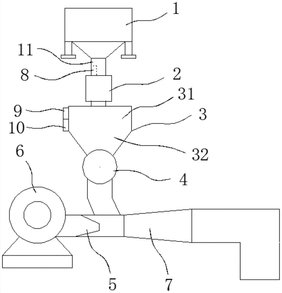
[0024] like figure 1 and figure 2 As shown, a filling system that can automatically adjust the humidity includes a filter 1, a dryer 2, a feed bin 3, a rotary feeder 4, an injector 5, a fan 6, a filling pipe 7, a humidity sensor 8, A processor 9 and a control circuit 10, the feed end of the filter 1 is introduced into the tailings slurry through a pipeline, the discharge end of the filter 1 is communicated with the upper end of the dryer 2 through a feeding pipe 11, the The lower end of the dryer 2 extends into the feed bin 3, the lower end of the feed bin 3 communicates with the upper end of the rotary feeder 4, and the lower end of the rotary feeder 4 extends into the filling In the pipeline 7, the injector 5 i...


PUM


Abstract

The invention relates to a filling system capable of automatically adjusting the humidity, comprising a filter, a dryer, a feed bin, a rotary feeder, an injector, a fan, a filling pipe, a humidity sensor, a processor, and a control circuit. The discharge end of the filter is communicated with the upper end of the dryer through a blanking pipe. The dryer extends into the feed bin. The feed bin is communicated with the upper end of the rotary feeder. The rotary feeder extends into the filling pipe. The injector is arranged at one side of the filling pipe. The fan is arranged at a side, away from the filling pipe, of the injector, and the fan is communicated with the injector. The discharge port of the filling pipe is disposed at a side, away from the injection orifice of the injector, of the lower end of the rotary feeder. The humidity sensor is fixedly arranged on the inner wall of the blanking pipe. The humidity sensor and the processor are connected by a line. The processor and the signal end of the control circuit are connected by a line. The output power end of the control circuit and the dryer are connected by a line. The filling system of the invention can automatically adjust the humidity of tailings, tailings are not easy to condensate, and the transmission efficiency is high.

Description

technical field [0001] The invention relates to the technical field of mineral machinery, in particular to a filling system capable of automatically adjusting humidity. Background technique [0002] At present, in mining operations, the exploitation of underground resources continuously destroys the balance of the original underground material composition, groundwater flow field, and original rock stress field, and forms an underground goaf. When the mining operation process does not exceed the set control range, the operation process is safe; when the mining operation process is out of control and exceeds the set control range, such as roof fall, water inrush, surface subsidence, debris flow or Mine safety accidents such as surface water influx underground, large-scale ground pressure activities, etc. The occurrence of these safety accidents is closely related to the existence of gobs. If high-quality filling is carried out in the goaf during the mining operation, the abo...

Claims


Application Information

Patent Timeline
Patent Type & Authority Patents(China)
IPC IPC(8): E21F15/10F26B25/22
CPCE21F15/10F26B25/22
Inventor 李力张捷钟传新
Owner 缪小忠
Why Eureka
Try Eureka