Horizontally-opposite diaphragm type electric vacuum pump

An electric vacuum pump, horizontally opposed technology, applied in the direction of variable capacity pump components, pumps, pump components, etc., can solve the problems of increased volume and relatively high requirements for parts size, and achieves reduction in volume, reduction of ineffective residues, and structure. Simple and compact effect

Inactive Publication Date: 2015-12-09
SHIJIAZHUANG JIAXIN AUTOMOTIVE BRAKE SYST
View PDF4 Cites 4 Cited by
  • Summary
  • Abstract
  • Description
  • Claims
  • Application Information

AI Technical Summary

Problems solved by technology

The existing vacuum pumps have put forward two new indicators of start-up time characteristics and recovery time characteristics in evaluating the pumping rate indicators to meet the needs of automotive products. To meet the requirements of these characteristics, it is necessary to increase the displacement of the vacuum pump , that is to increase the volume of the cylinder, so that the volume of the vacuum pump can be increased, but the design of the engine room of the car is relatively compact, and the requirements for the size of the parts are relatively high.

Method used


Image

  • Horizontally-opposite diaphragm type electric vacuum pump
  • Horizontally-opposite diaphragm type electric vacuum pump

Examples


Embodiment Construction

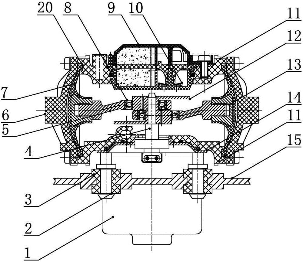
[0013] Such as figure 1 As shown, a horizontally opposed diaphragm type electric vacuum pump of the present invention includes a pump body 11 and a fixed bracket 15. A motor 1 is installed on the fixed bracket 15 through a motor fixing screw 2. Vibration rubber 3 is used to enhance the anti-seismic performance of the device. The motor 1 is a DC motor, which is directly powered by the battery of the car. The motor side cover 14 on the top of the motor 1 is connected to the bottom of the pump body 11 through bolts, and the bottom of the pump body 11 is provided with a through hole. The motor shaft 4 extends into the inside of the pump body 11 through the through hole, and two left and right horizontally opposite eccentric cranks 12 are installed on the motor shaft 4 . A connecting rod 5 is movably connected to the eccentric crank 12 , and a bearing 8 is arranged at the joint. The other end of the connecting rod 5 is connected to a diaphragm assembly 13 , and the diaphragm asse...


PUM


Abstract

The invention relates to a vacuum pump providing vacuum assisting power for an automobile braking master pump and aims to provide a horizontally-opposite diaphragm type electric vacuum pump which is small in size, large in exhaust amount and convenient to machine. The horizontally-opposite diaphragm type electric vacuum pump comprises a fixed support, a motor and a pump body. Two eccentric cranks which are horizontally arranged in the left and right direction are installed on a motor shaft in the pump body and connected with connecting rods. The other ends of the connecting rods are connected with diaphragm assemblies which are wrapped in diaphragms. The edges of the diaphragms are fixed to the pump body. End covers are installed at the two ends of the pump body. A sealed work cavity is formed between each diaphragm and the corresponding end cover. Two sets of installing holes are machined in the inner side of each end cover, and each upper installing hole and each lower installing hole are provided with an air inflow valve and an air outflow valve respectively. Each air inflow valve and the corresponding air outflow valve are communicated with an air inflow channel and an air outflow channel respectively. Each air inflow channel is connected with an air outflow pipeline. The air outflow channels are communicated with the interior of the pump body. An exhaust port is formed in the upper portion of the pump body.

Description

technical field [0001] The invention relates to a vacuum pump, in particular to a horizontally opposed diaphragm type electric vacuum pump used for providing vacuum boost for a master brake cylinder of an automobile. Background technique [0002] As an energy-saving, pollution-free ideal "zero-emission" vehicle, electric vehicles are increasingly receiving widespread attention and attention from all over the world. However, due to technical constraints and actual national conditions, most of the various researches on electric vehicles in our country can only be modified on the basis of existing internal combustion engine vehicles. The vast majority of cars use vacuum-assisted servo braking systems to use both manpower and power. For the braking system of traditional gasoline engine small gas vehicles, the vacuum source of the vacuum booster comes from the engine intake manifold. For pure electric vehicles or fuel cell vehicles converted from traditional models, after the en...

Claims


Application Information

Patent Timeline
Patent Type & Authority Applications(China)
IPC IPC(8): F04B45/047F04B37/14F04B39/10F04B39/00
Inventor 李建忠
Owner SHIJIAZHUANG JIAXIN AUTOMOTIVE BRAKE SYST
Why Eureka
Try Eureka